Low-heating laser cutting machine

A technology of laser cutting machine and laser cutting head, which is applied in laser welding equipment, welding/welding/cutting items, applications, etc., can solve the problems of unsightly incision of pipe body, heavy pipe gravity, troublesome cutting, etc., and prevent cutting deviation The effect of moving, cutting size is accurate, and it is easy to unload

Inactive Publication Date: 2020-07-10
安徽汉超智能装备科技有限公司
View PDF7 Cites 7 Cited by
  • Summary
  • Abstract
  • Description
  • Claims
  • Application Information

AI Technical Summary

Problems solved by technology

[0002] When the products with pipe structure are cut to length, laser cutting devices are often used, especially for plastic pipes. When laser cutting, it is easy to cause plastic melting, resulting in unsightly cuts of the pipe body. Highly rotating cutting saw blades are used. For cutting, it is often because the diameter of the saw blade cannot meet the cutting requirements of large-diameter pipes, resulting in troublesome cutting. If the cutting method of rotating the saw blade at high speed around the pipe body is used, it is extremely dangerous. If the method of rotating the pipe body is used , the gravity of the pipe is heavier, and the energy consumption is larger

Method used


Image

  • Low-heating laser cutting machine
  • Low-heating laser cutting machine
  • Low-heating laser cutting machine

Examples


Embodiment 1

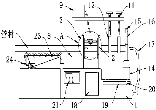
[0025] refer to Figure 1-3 , a low-heat laser cutting machine, including a machine platform 1, the left side of the machine platform 1 is provided with a conveying mechanism, the conveying mechanism includes a conveying platform fixedly connected to the left side of the machine platform 1, and a conveyor belt 23 is installed on the upper surface of the conveying platform , the conveyor belt 23 is driven by a servo drive motor 24, and the servo drive motor 24 is coupled with a PLC controller 21.

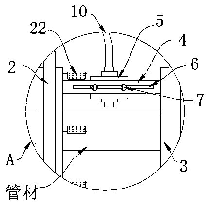
[0026] The upper surface of the machine table 1 is fixedly connected with two ring frames 2, and the inner arc surfaces of the rings of the two ring frames 2 are equipped with large-diameter bearings 3, and the inner ring of the large-diameter bearing 3 located on the left side of the laser cutting head 5 A plurality of control handles 22 arranged equidistantly in the circumferential direction are installed on the right side of the motor, and the opposite surfaces of the inner rings ...

Embodiment 2

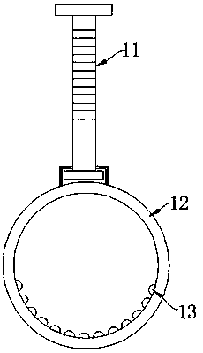
[0031] refer to Figure 4-5 , and the difference from Embodiment 1 is that the right end front of the machine table 1 is provided with a scale mark, the front of the fixed frame 8 is provided with a sliding groove 25, and the inside of the sliding groove 25 is slidably connected with a slider, and the front of the slider is fixedly connected with an electronic Laser pointer 26; The front of fixed frame 8 is also provided with scale mark, and the material of slide block is magnetic block, and the inwall of sliding groove 25 is embedded with the metal bar that produces magnetic force adsorption with magnetic block.

[0032] In this embodiment, by setting up the sliding groove 25 on the front of the fixed frame 8, and the inside of the sliding groove 25 is embedded with a metal strip, which is magnetically adsorbed with the slider to facilitate the positioning of the electronic laser pointer 26, thereby facilitating the electronic laser pointer. The 26 position adjustment can acc...


PUM


Abstract

The invention discloses a low-heating laser cutting machine. The low-heating laser cutting machine comprises a machine table, a conveying mechanism is arranged on the left side of the machine table, two circular frames are fixedly connected to the upper surface of the machine table, and large-diameter bearings are mounted on the circular inner arc surfaces of the two circular frames. According tothe low-heating laser cutting machine, a servo drive motor is utilized to drive a conveyor belt and drives a pipe to horizontally move, the large-diameter bearings and a mounting frame are utilized todrive a laser cutting head to rotate around the pipe, a handle is held by hand during cutting, rotated by 180 degrees clockwise and then rotated by 370 degrees anticlockwise to achieve rotary cuttingof the pipe, and winding of a reflecting hose is avoided. Meanwhile, the laser cutting machine is provided with an electric telescopic rod to drive a lifting positioning plate, so that cutting sizingof the pipe and pipe discharging are facilitated. Meanwhile, cold air generated by a refrigerating device is conveyed into a pipe body through a cold conveying hose, so that the phenomenon that a cutof the pipe body made of plastic is melted during cutting is avoided, and the cutting size is more accurate.

Description

technical field [0001] The invention relates to the technical field of laser cutting, in particular to a low-heat laser cutting machine. Background technique [0002] When the products with pipe structure are cut to length, laser cutting devices are often used, especially for plastic pipes. When laser cutting, it is easy to cause plastic melting, resulting in unsightly cuts of the pipe body. Highly rotating cutting saw blades are used. For cutting, it is often because the diameter of the saw blade cannot meet the cutting requirements of large-diameter pipes, resulting in troublesome cutting. If the cutting method of rotating the saw blade at high speed around the pipe body is used, it is extremely dangerous. If the method of rotating the pipe body is used , the gravity of the pipe is heavier and the energy consumption is larger. [0003] Therefore, the method of laser rotary cutting is safe and does not need to rotate the pipe. The only problem to be solved is to avoid the ...

Claims


Application Information

Patent Timeline
Patent Type & Authority Applications(China)
IPC IPC(8): B23K26/38B23K26/402B23K26/14B23K26/10B23K26/70
CPCB23K26/38B23K26/402B23K26/14B23K26/103B23K26/702B23K2101/06B23K2103/42
Inventor 陈宏
Owner 安徽汉超智能装备科技有限公司
Why Eureka
Try Eureka