Roller column rotary rolling machine

A roll column and rolling mill technology, applied in the direction of metal rolling stand, metal rolling mill stand, metal rolling, etc., can solve the problems of small unformed area, low spin rolling yield, material plastic accumulation, etc., and reach the forming area. Small, good molding quality and yield, easy to operate

Active Publication Date: 2020-08-18
TAIYUAN UNIVERSITY OF SCIENCE AND TECHNOLOGY
View PDF8 Cites 2 Cited by
  • Summary
  • Abstract
  • Description
  • Claims
  • Application Information

AI Technical Summary

Problems solved by technology

Ball rolling is a continuous local plastic forming process using balls as deformation tools. It has the advantages of small deformation area and large forming force, but at t

Method used


Image

  • Roller column rotary rolling machine
  • Roller column rotary rolling machine
  • Roller column rotary rolling machine

Examples


Example Embodiment

[0026] The present invention will be further described below with reference to the accompanying drawings and embodiments.

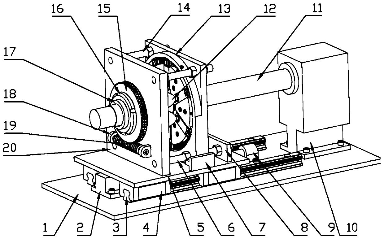
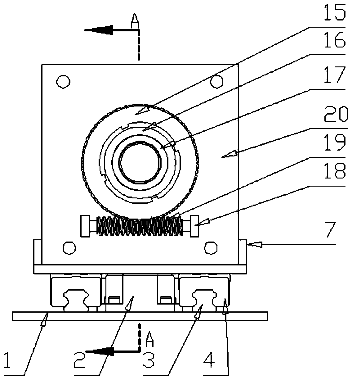
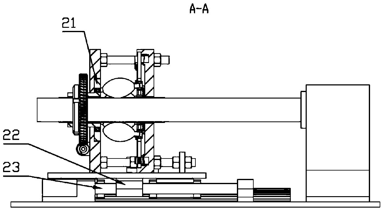
[0027] like Figure 1-7 As shown, a roll rolling mill in this embodiment includes a base plate 1 and a mandrel driving mechanism, and further includes a feed mechanism, an angle adjustment mechanism and a depression adjustment mechanism 13, and the feed mechanism is arranged on the base plate. On the upper plane of 1, the angle adjustment mechanism and the pressing adjustment mechanism 13 are arranged on the upper plane of the feeding platform 5 in the feeding mechanism, and the core mold driving mechanism is arranged at one end of the upper plane of the base plate 1;

[0028] The core mold driving mechanism includes a core mold 11 and a core mold driving motor 10. The core mold driving motor 10 is arranged at one end of the upper plane of the base plate 1, and one end of the core mold 11 is connected to the output shaft of the core mold driving motor 10....


PUM


Abstract

The invention belongs to the technical field of rolling equipment, and particularly relates to a roller column rotary rolling machine. The technical problems that in the existing ball spinning process, material plastic accumulation is likely to be generated in an unformed area, and the spinning yield is low are mainly solved. According to the technical scheme, the roller column rotary rolling machine comprises a bottom plate and a core mold driving mechanism and further comprises a feeding mechanism, an angle adjusting mechanism and a pressing-down adjusting mechanism, the feeding mechanism isarranged on the upper plane of the bottom plate, the angle adjusting mechanism and the pressing-down adjusting mechanism are arranged on the upper plane of a feeding platform in the feeding mechanism, and the core mold driving mechanism is arranged at one end of the upper plane of the bottom plate. The rotary rolling machine can change the rotary rolling angle and the rolling reduction of rollercolumns, can ensure that the rolling reduction of each roller column is the same, and has the advantages of being simple in structure, compact in equipment, easy and convenient to operate and capableof easily achieving adjustment of the rotary rolling angle.

Description

technical field [0001] The invention belongs to the technical field of rolling equipment, and in particular relates to a roller column spinning mill. Background technique [0002] Spinning is one of the main technological means of steel pipe forming. For precision thin-walled pipes, ball spinning is often used for processing at this stage. Ball spinning is a continuous local plastic forming process using balls as a deformation tool. It has the advantages of small deformation area and large forming force, but at the same time, due to the small unformed area, during the spinning process, the unformed area is prone to material plasticity. Accumulation, resulting in low spin rolling yield. SUMMARY OF THE INVENTION [0003] The purpose of the present invention is to solve the defects existing in the existing ball spinning, and to provide a roll rolling machine, which can change the rolling angle and reduction of the rolls, and can ensure that the reduction of each roll is the ...

Claims


Application Information

Patent Timeline
IPC IPC(8): B21B19/06B21B31/16
CPCB21B19/06B21B31/16
Inventor 赵春江周梓朋白峭峰李维壮许镱巍都嘉鑫李海潮
Owner TAIYUAN UNIVERSITY OF SCIENCE AND TECHNOLOGY
Why Eureka
Try Eureka