A vibration damping device for a hybrid power unit of an unmanned aerial vehicle

A technology of hybrid power and vibration damping device, which is applied in the directions of power plant, power plant arrangement/installation, unmanned aerial vehicle, etc., can solve the problems of single vibration damping method, fast vibration speed and large engine amplitude, etc. Achieve the effect of improving stability and vibration reduction, compact structure design, and reducing workload

Active Publication Date: 2021-12-03
扬州翊翔航空科技有限公司
View PDF6 Cites 0 Cited by
  • Summary
  • Abstract
  • Description
  • Claims
  • Application Information

AI Technical Summary

Problems solved by technology

3. The loading space of the UAV is limited and the battery life is affected by the flight weight. The volume and weight of the vibration reduction device should be as small as possible
[0005] 1. There is no design for the characteristic of "drone is extremely sensitive to vibration", the vibration reduction method is single, and the vibration reduction effect needs to be verified
[0006] 2. The engine has a large amplitude and a fast vibration speed. The motor is directly connected to the vibration source as the actuator of active vibration reduction. Therefore, the response speed of the motor needs to be fast. This not only has higher requirements for the motor, but also increases the cost. increase the complexity of the control system
[0007] 3. The structural design is not compact, the space utilization rate is not high, and the mass of the vibration damping device is large, which increases the weight of the drone and reduces the load-bearing capacity of the drone

Method used


Image

  • A vibration damping device for a hybrid power unit of an unmanned aerial vehicle
  • A vibration damping device for a hybrid power unit of an unmanned aerial vehicle
  • A vibration damping device for a hybrid power unit of an unmanned aerial vehicle

Examples


Embodiment Construction

[0028] Below in conjunction with specific embodiment, further illustrate the present invention, it should be understood that these embodiments are only used to illustrate the present invention and are not intended to limit the scope of the present invention, after reading the present invention, those skilled in the art will understand various equivalent forms of the present invention All modifications fall within the scope defined by the appended claims of this application.

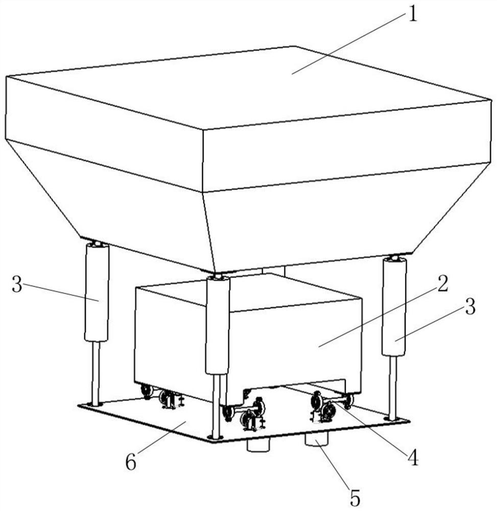
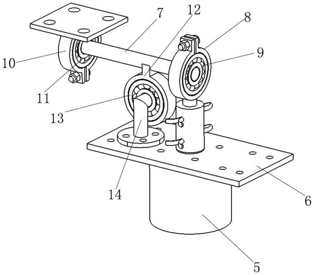
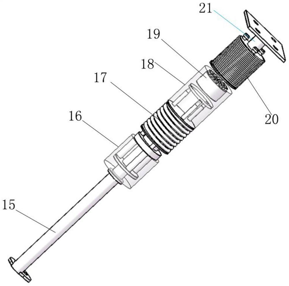
[0029] like Figure 1-5As shown, a vibration damping device of a hybrid power unit of an unmanned aerial vehicle includes a loading platform 6 arranged under the fuselage 1 of the unmanned aerial vehicle, and the hybrid power unit 2 of the unmanned aerial vehicle is arranged on the loading platform 6, and the hybrid power A first damping mechanism 4 is provided between the unit 2 and the loading platform 6, and a second damping mechanism 3 is provided between the loading platform 6 and the fuselage 1; Fo...


PUM


Abstract

The invention discloses a vibration damping device of a hybrid power unit of an unmanned aerial vehicle in the technical field of unmanned aerial vehicles. The device includes a loading platform, the hybrid power unit of the UAV is arranged on the loading platform, a first vibration reduction mechanism is provided between the hybrid power unit and the loading platform, and a second vibration reduction mechanism is provided between the loading platform and the fuselage; The second damping mechanism includes a passive damping assembly and a magnetic damping assembly; the first damping mechanism includes a voice coil motor, the motor shaft of the voice coil motor is connected to the first bearing seat through a coupling, and the first bearing seat is provided with a first Self-aligning bearing, the bottom of the hybrid power unit is provided with a second bearing seat, and a second self-aligning bearing is arranged in the second bearing seat, and a horizontally arranged strut is installed between the first self-aligning bearing and the second self-aligning bearing; the strut The lower end is provided with a supporting part for supporting it, and the supporting part is arranged close to the first self-aligning bearing. The invention has the advantages of compact structure design and remarkable vibration damping effect.

Description

technical field [0001] The invention relates to the technical field of unmanned aerial vehicle equipment, in particular to a vibration damping device for a hybrid power unit of an unmanned aerial vehicle. Background technique [0002] Small multi-rotor drones refer to drones with an empty mass of ≤15kg and ≥4kg, and a maximum take-off mass of ≤25kg and ≥7kg, driven by electricity, with vertical take-off and landing, hovering in the air, and low power coupling. Fast response and other advantages. It can be used in aviation forestry and fire detection and other fields. The battery life of the small multi-rotor UAVs currently on sale is basically 20 minutes, which is far from enough for the rich functions of UAVs. For example, the traffic in the northeast forest area is inconvenient, and the patrol operation radius is 100-300km. The endurance of the current small multi-rotor drones cannot meet the operation requirements at all. The main factors affecting battery life are fli...

Claims


Application Information

Patent Timeline
Patent Type & Authority Patents(China)
IPC IPC(8): B64D27/26B64D27/02B64C39/02
CPCB64D27/26B64D27/02B64C39/02B64D2027/266B64D2027/026B64U50/11B64U50/19
Inventor 闫凤军李宝民涂楷费冬青
Owner 扬州翊翔航空科技有限公司
Why Eureka
Try Eureka