Optical fiber vibration measurement device and method with improved light source noise

A fiber optic vibration and measurement device technology, which is applied to the measurement device, uses optical devices to transmit sensing components, and measures ultrasonic/sonic/infrasonic waves. Measurement accuracy, improvement of measurement accuracy, and effect of avoiding frequency drift

Active Publication Date: 2022-02-18
珠海任驰光电科技有限公司
View PDF11 Cites 0 Cited by
  • Summary
  • Abstract
  • Description
  • Claims
  • Application Information

AI Technical Summary

Problems solved by technology

By calculating the spacing D AB and D CD The proportional relationship of the laser phase noise can eliminate the influence of the laser phase noise on the performance of the sensing system, compensate the measurement phase drift caused by the frequency drift in real time, and improve the measurement accuracy of the external vibration signal. However, it is a digital signal processing method, which does not fundamentally reduce the Laser phase noise makes it difficult to further improve the measurement accuracy of external vibration signals

Method used


Image

  • Optical fiber vibration measurement device and method with improved light source noise
  • Optical fiber vibration measurement device and method with improved light source noise
  • Optical fiber vibration measurement device and method with improved light source noise

Examples


Embodiment 1

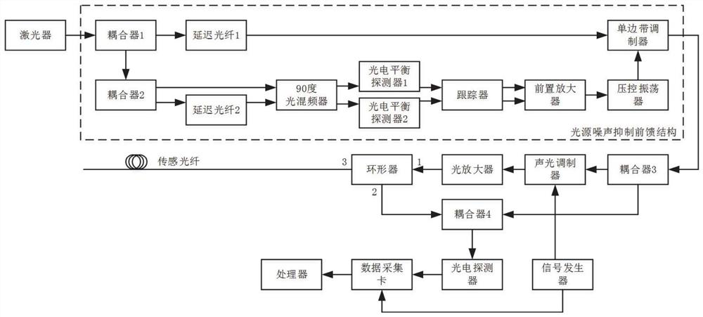
[0049] A typical embodiment of the present disclosure, as Figure 1 - Figure 2 , The proposed improved optical noise source a vibration measuring device.

[0050] Which apparatus comprising: a laser light source feedforward noise suppressing structure, the coupler 3, the acousto-optic modulator, erbium doped fiber amplifier, a circulator, a sensing fiber, coupler 4, a photodetector, a data acquisition card, and a signal generator processor.

[0051] After exiting the laser linewidth narrower continuous light source through a feedforward noise suppressing structure, entering through the power coupler having a specific ratio 3, is divided into two, wherein all the way through the continuous light having the acousto-optic modulator frequency shift function, having converted to light having a specific width and pulse period, and then after the optical amplifier power compensator into the annular port 1, and then emitted through the annular port to the sensing fiber 3, acquired carrying...

Embodiment 2

[0063] Another exemplary embodiment of the present disclosure, as Figure 1 - Figure 2 , The proposed method for the optical fiber vibration measurement noise source improved.

[0064] Step 1, a continuous laser output wavelength of 1330nm or 1550nm light:

[0065]

[0066] Wherein, A represents the amplitude of the light wave, v 0 Representative light wave frequency, constant 193.5THz (corresponding to the wavelength of 1550nm) or 229.0THz (corresponding to the wavelength of 1310nm), θ (t) representative of the phase noise light, t represents time.

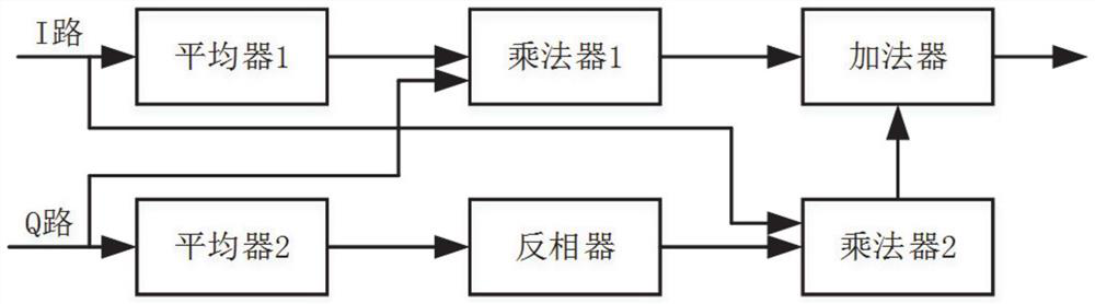
[0067] Step 2, a continuous laser light into two paths, wherein a channel using classical Mach - Zehnder interferometer, to give two (I and Q-) orthogonal interference signal:

[0068] I (t) = B cos (2πν 0 τ + Δθ (t)) (2)

[0069] Q (t) = B sin (2πν 0 τ + Δθ (t)) (3)

[0070] Δθ (t) = θ (t) -θ (t-τ) (4)

[0071] Wherein, B represents an interference signal amplitude, Δθ (t) represents a first order source phase noise difference, τ r...


PUM


Abstract

The present disclosure provides an optical fiber vibration measurement device and method for improving light source noise, and relates to the field of optical fiber distributed vibration measurement. The mutually orthogonal two-way interference optical signals are output to the photoelectric balance detector 1 and the photoelectric balance detector 2 respectively, converted into two-way interference electrical signals, and output to the tracker; using the light source noise suppression feedforward structure, the laser output The continuous light suppresses the phase noise, which is added to the classic measurement device to reduce the phase noise of the laser and further improve the measurement accuracy of the external vibration signal.

Description

Technical field [0001] The present disclosure relates to the field of fiber distributed vibration measurement, and more particularly to a fiber vibration measuring device and method for improved light source noise. Background technique [0002] The statement of this section is merely the background technology related to the present disclosure, and it is not necessarily constituting the prior art. [0003] The optical time domain reflection measurement technology is based on the rear-directional scattering principle of light, and the rear scattering optical wave generated when the pulse light wave is propagated in the optical fiber, which can be used to measure fiber attenuation. , Joint loss, fiber-flex point positioning, and understanding of the distribution of the fiber along the length of the fiber, etc., is an indispensable technique for cable construction, maintenance and monitoring. [0004] With the continuous improvement of measurement technology, the measurement such as ...

Claims


Application Information

Patent Timeline
Patent Type & Authority Patents(China)
IPC IPC(8): G01H9/00G01D5/353
CPCG01H9/004G01D5/35361G01D5/35329
Inventor 于淼王忠民常天英杨先勇崔洪亮杨先进郑志丰程立耀吴崇坚张耀鲁
Owner 珠海任驰光电科技有限公司
Why Eureka
Try Eureka