
A bearing preloading device

A technology for bearings and bearing housings, which is applied in the field of bearing preloading, can solve the problems of lag error, poor control, and high preloading costs, and achieve the effects of reducing preloading costs, improving preloading efficiency, and expanding the preloading range

Active Publication Date: 2022-02-11
JIANGSU UNIV OF TECH
View PDF0 Cites 0 Cited by
  • Summary
  • Abstract
  • Description
  • Claims
  • Application Information

AI Technical Summary

Problems solved by technology

[0003] In order to solve the problems of high cost, poor control, and excessive hysteresis error in the existing bearing preloading, the present invention provides a bearing preloading device, including bearings, bearing seats, inclined sleeves, collars, and steps Shaft and cover plate, the inner ring of the bearing is installed in cooperation with the stepped shaft, the outer ring of the bearing is installed in interference fit with the inner ring of the inclined sleeve, and the outer side of the inclined sleeve is installed in cooperation with the inner ring of the collar , the outer surface of the inclined sleeve is tapered, the shape of the inner ring of the collar corresponds to the shape of the outer surface of the inclined sleeve, the outer ring of the collar is slidably arranged in the bearing seat, and the two sides of the bearing seat Both are fixed with the cover plate, the cover plate cooperates with the stepped shaft to axially fix the inner ring of the bearing, and the cover plate is also used to hold the bearing close to the outer side of the inclined sleeve with a smaller size The outer ring at one end also includes a pre-tension mechanism for pushing the outer ring of the bearing to move axially, and the pre-tension mechanism is arranged on the cover plate near the larger end of the outer side of the oblique sleeve

Method used


Image

  • A bearing preloading device
  • A bearing preloading device
  • A bearing preloading device

Examples


Embodiment 1

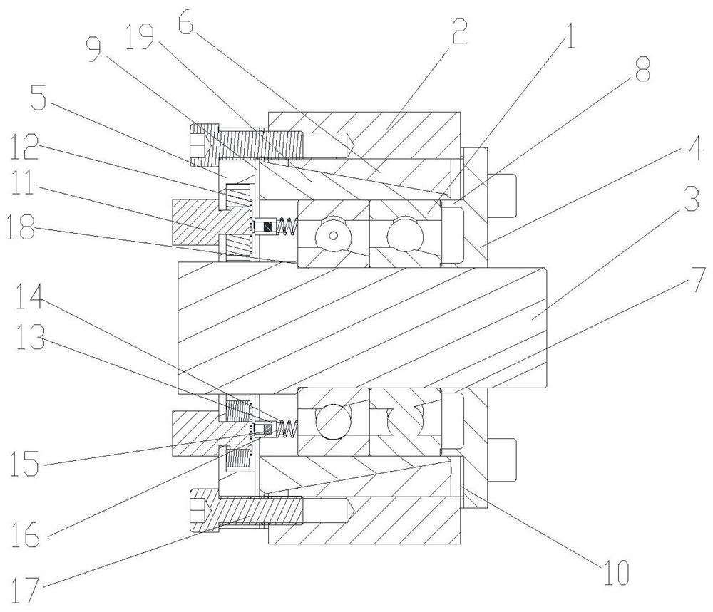
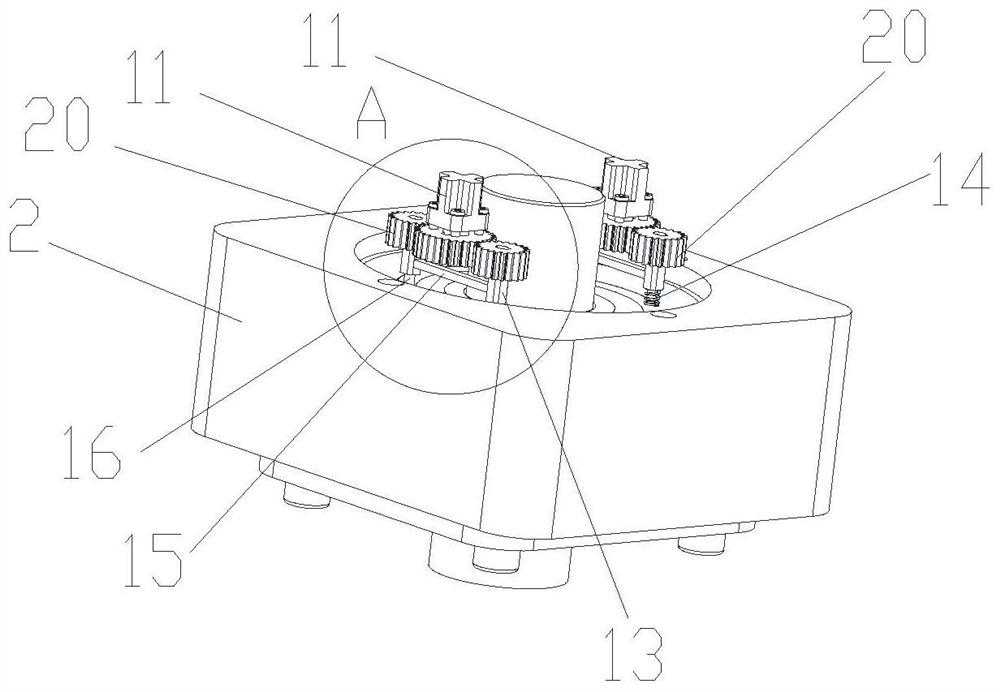
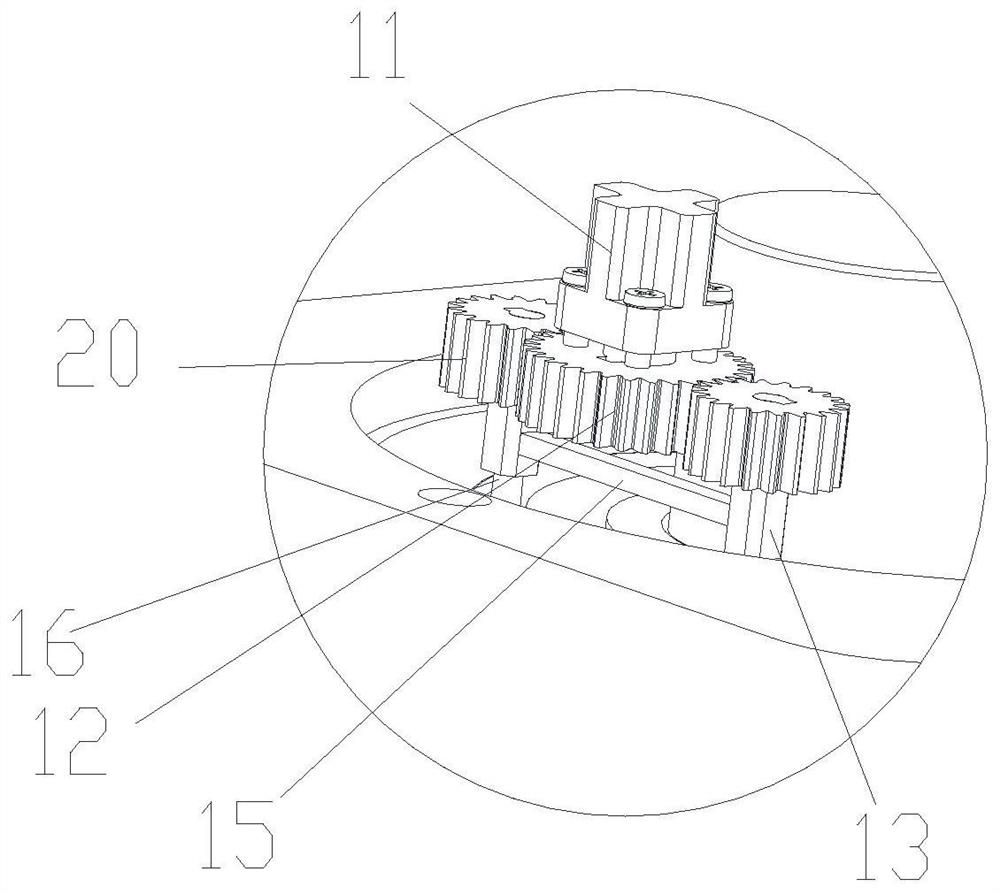
[0021] As shown in the figure, a bearing pretightening device includes a bearing 1, a bearing seat 2, a slanted sleeve 19, a collar 6, a stepped shaft 3 and a cover plate, the inner ring of the bearing 1 is installed in cooperation with the stepped shaft 3, The outer ring of the bearing 1 is installed in interference fit with the inner ring of the slanted sleeve 19, and the outer side of the slanted sleeve 19 is installed in cooperation with the inner ring of the collar 6. The outer surface of the slanted sleeve 19 is tapered, and the The shape of the inner ring of the collar 6 corresponds to the shape of the outer surface of the inclined sleeve 19, the outer ring of the collar 6 is slidably arranged in the bearing seat 2, and the cover plates are fixed on both sides of the bearing seat 2 , the cover plate cooperates with the stepped shaft 3 to axially fix the inner ring of the bearing 1, and the cover plate is also used to resist the outer ring of the bearing 1 near the smalle...

Embodiment 2

[0026] The only difference from the first embodiment above is that the cover plate is divided into a front cover plate 5 and a rear cover plate 4, the front cover plate 5 is located at the larger end of the outer side of the inclined sleeve 19, and the pre-tensioning mechanism is arranged at On the front cover 5, a first protrusion 7 for resisting the inner ring of the bearing 1 is provided on the front cover 5, and a first protrusion 7 for resisting the outer ring of the bearing 1 is provided on the rear cover 4. The second protrusion 8. The rear cover 4 is arranged near the end of the outer surface of the inclined sleeve 19 with a smaller size, the rear cover 4 is provided with a second protrusion 8 for resisting the outer ring of the bearing 1, and the front cover 5 is provided with a first protrusion 7 For resisting the inner ring of the bearing 1 , the step 18 of the stepped shaft 3 is arranged close to the rear cover 4 , and the step 18 of the stepped shaft 3 cooperates ...


PUM


Abstract

The present invention relates to a bearing pretensioning device, comprising a bearing, a bearing seat, a slanted sleeve, a collar, a stepped shaft and a cover plate, the inner ring of the bearing is installed in cooperation with the stepped shaft, the outer ring of the bearing is fitted with the The inner ring of the inclined sleeve is installed with interference fit, and the outer side of the inclined sleeve is fitted with the inner ring of the sleeve. Correspondingly, the outer ring of the collar is slidably arranged in the bearing seat, and the cover plate is fixed on both sides of the bearing seat, and the cover plate cooperates with the stepped shaft to axially fix the bearing The inner ring, the cover plate is also used to resist the outer ring of the bearing near the smaller end of the outer side of the slant sleeve, and also includes a preload mechanism for pushing the outer ring of the bearing to move axially. The invention not only expands the range of pre-tightening, but also reduces the cost of pre-tightening.

Description

technical field [0001] The invention relates to the technical field of bearing pretensioning, in particular to a bearing pretensioning device. Background technique [0002] The preloading of rolling bearings is to use appropriate methods to make a certain pre-deformation between the bearing rolling body and the inner and outer rings, so as to keep the inner and outer rings of the bearing in a compressed state, so that the bearing runs with negative clearance or zero clearance. The clearance of the bearing under normal working conditions is zero or negative clearance is the best, which can ensure the rotation accuracy of the shaft to the maximum extent, reduce the vibration and noise of the shaft, and prolong the life of the bearing. In the prior art, most of the pre-tightening of the bearing before work is purely mechanical, through the interaction of forces, and the opposite force on the sleeve is used to apply a certain load to the bearing, so as to achieve the effect of p...

Claims


Application Information

Patent Timeline
Patent Type & Authority Patents(China)
IPC IPC(8): F16C35/063F16C33/58F16H57/00
CPCF16C35/063F16C33/583F16H57/00
Inventor 徐旭松叶超朱敏浩孙志英
Owner JIANGSU UNIV OF TECH
Learn More