Ambulance reloading method
A technology for ambulances and ambulance cabins, applied in the field of ambulances, which can solve the problems of limited equipment, increased rescue time, and the inability to carry rescue equipment for patients, so as to achieve good temporary rescue, save replacement time, and improve rescue conditions.
- Summary
- Abstract
- Description
- Claims
- Application Information
AI Technical Summary
Problems solved by technology
Method used
Image
Examples
Embodiment 1
[0049] This embodiment discloses a replacement ambulance, which can carry different ambulance compartments on the vehicle body, realize flexible matching for different patients, make full use of the advantages of replacement, and improve the rescue conditions of the ambulance at the accident scene and inside the ambulance. Provide better temporary care until the ambulance reaches the hospital.
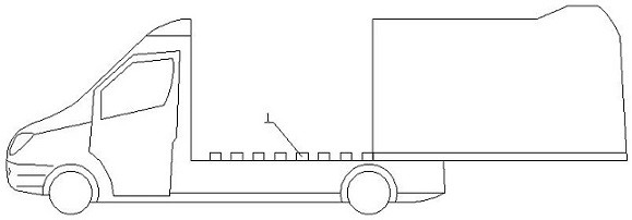
[0050] combine figure 1 As shown, a replacement ambulance includes a car body and an ambulance cabin. The car body and the ambulance cabin are split structures. The design of the split structure enables the body of the same ambulance to carry different ambulance cabins. Different ambulance equipment is preset in the ambulance cabin, which avoids that the unified ambulance equipment cannot adapt to different rescue needs;
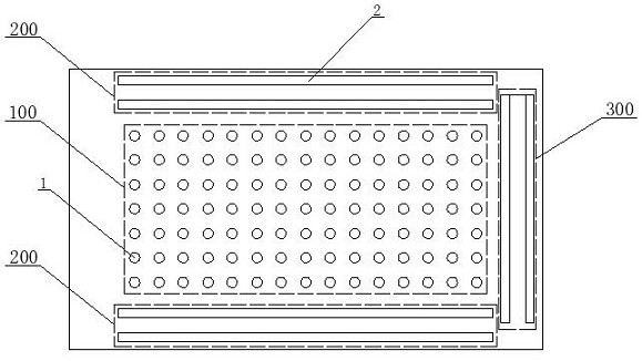
[0051] combine figure 2 and image 3 As shown, the rear end of the car body is provided with a loading plane, the middle of which is the insertion area 100, and ...
Embodiment 2
[0058] This embodiment provides a clamping mechanism for ambulance replacement on the basis of Embodiment 1. The clamping mechanism can be hidden in the loading plane, and when clamping is required, it can be Stretch out to clamp the clamping block 4;
[0059] combine Figure 5 and Figure 6 As shown, the clamping mechanism 2 includes: a splint 2-1, a first splint strut 2-2, a second splint strut 2-3 and a strut swivel seat 2-4, the two splints 2- 1 are arranged in parallel, and the opposite sides of the two splints 2-1 jointly form the clamping mouth of the clamping mechanism 2, a splint receiving groove is provided on the loading plane, and the bottom of each of the splints 2-1 is vertically provided with At least two first splint struts 2-2, the lower end of each first splint strut 2-2 is hingedly connected to the upper end of a second splint strut 2-3, each second splint strut 2-3 The lower end of each is fixedly connected with a strut swivel seat 2-4.
[0060] Specifi...
Embodiment 3
[0065]This embodiment discloses a structure of a plug-in mechanism 3 on the basis of embodiment 1 or 2, which can realize the plug-in mechanism at the bottom of the ambulance compartment to be plugged into the fixed column 1 from the side or rear;
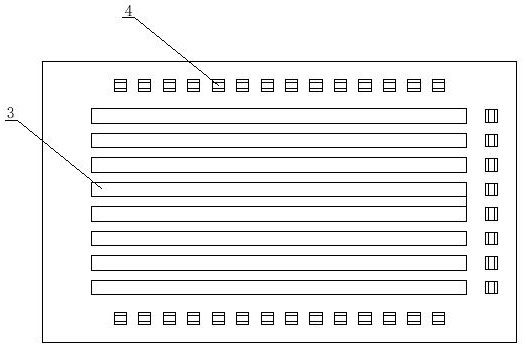
[0066] to combine image 3 As shown, the plug-in mechanism 3 is a strip-shaped plug-in strip, and several plug-in strips are arranged at intervals, and the side plug-in strips are interlaced with the fixed columns 1 arranged along the length direction of the mounting plane. Rear insertion strips arranged staggeredly along the fixed columns 1 arranged along the width direction of the loading plane;
[0067] The ambulance compartment located on the side of the vehicle body is inserted into the annular slot of the fixing column 1 from the side through the side inserting strip at the bottom when plugging in, and the ambulance compartment located at the rear of the vehicle body is inserted through the rear inserting strip at the bottom ...
PUM
 Abstract
Description
Claims
Application Information
 - R&D
- Intellectual Property
- Life Sciences
- Materials
- Tech Scout
- Unparalleled Data Quality
- Higher Quality Content
- 60% Fewer Hallucinations
Browse by: Latest US Patents, China's latest patents, Technical Efficacy Thesaurus, Application Domain, Technology Topic, Popular Technical Reports.
© 2025 PatSnap. All rights reserved.Legal|Privacy policy|Modern Slavery Act Transparency Statement|Sitemap|About US| Contact US: help@patsnap.com


