Binding device

A binding needle and needle loading technology, which is applied in the direction of nailing staple tools, nailing tools, manufacturing tools, etc., can solve the problems of large force, small contact area, user's hand fatigue and pain, etc. Easy to carry and relieve fatigue and pain

Pending Publication Date: 2020-12-01
宁波易恬工业设计有限公司
View PDF0 Cites 0 Cited by
  • Summary
  • Abstract
  • Description
  • Claims
  • Application Information

AI Technical Summary

Problems solved by technology

This kind of binding device completely relies on the direct pressure of the hand during the binding process, which requires a large force, and the force point is on the head of the gland, and the contact area with the operator's hand is small, and it is easy to cause damage when used for a long time. hand fatigue pain
In addition, the cover is inclined relative to the base and the staple case, so the cover is easy to open relative to the staple case, and it is very inconvenient to carry around

Method used


Image

  • Binding device
  • Binding device
  • Binding device

Examples


Embodiment Construction

[0031] The present invention will be described in further detail below in conjunction with the accompanying drawings and specific embodiments.

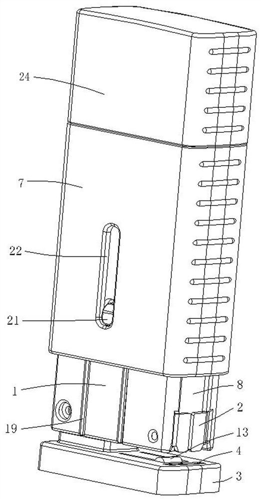
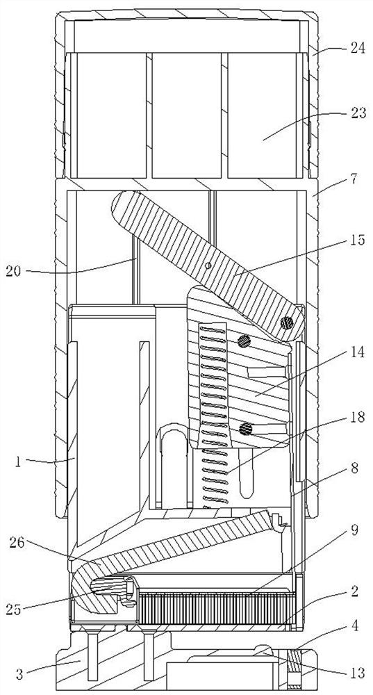
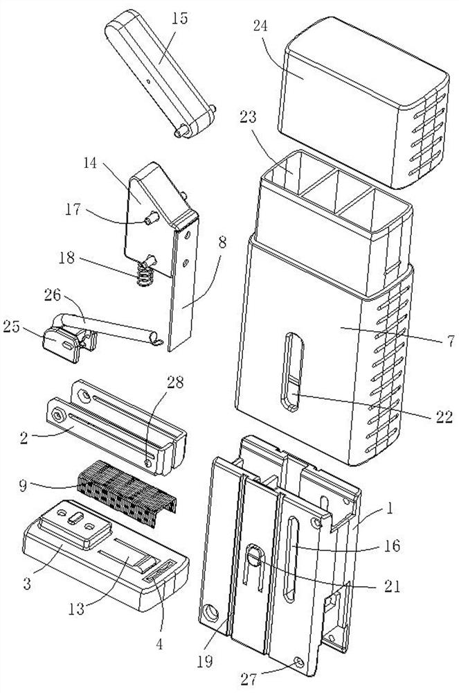
[0032] refer to Figure 1~Figure 10 , a binding device, including a main body 1, and a needle box 2 installed on the main body, a base 3 is provided below the needle box, and a bending groove 4 is provided on the base, and the bending groove 4 is used for The staples are bent;

[0033] The needle box 2 has a needle slot 5 for placing staples, and the end of the needle slot is provided with a drop hole 6 that is opposite to the bending slot and can pass through a single staple. 2 is provided with a needle pusher that can move the binding needle along the needle groove to the direction of the lower needle hole 6;

[0034] The main body 1 is slidably provided with a driver 7, and the main body is also movably provided with a needle pressing top plate 8 opposite to the needle drop hole. When the driver 7 is pressed, the driver will 1. ...


PUM


Abstract

The invention relates to a binding device which comprises a main body, a needle containing box and a base, and a bending groove is formed in the base. A needle groove is formed in the needle containing box, a needle descending hole is formed in the tail end of the needle groove, and a needle pushing device is arranged on the needle containing box. A driving piece is arranged on the main body in asliding mode, a pressing needle ejecting piece and a pressing driving piece are movably arranged on the main body, the driving piece slides relative to the main body and directly or indirectly drivesthe pressing needle ejecting piece to extend into the needle descending hole, and the binding needle is bent and nailed on an object to be bound under the cooperation of the bending groove and the pressing needle ejecting piece. The beneficial effects of the invention are that: the structure is adopted, the driving piece is directly pressed downwards to drive the needle pressing ejection piece toextend into the needle descending hole, the needle pressing ejection piece is matched with the bending groove to complete binding, the hand of an operator directly applies pressure to the driving piece, the contact area between the hand of the operator and the hand of the operator is large, fatigue and pain caused by long-time use of the hand of the operator are greatly relieved, and labor is saved. Moreover, the device is square in size and convenient to carry.

Description

technical field [0001] The invention relates to office equipment, in particular to a binding device. Background technique [0002] The binding device is a kind of office supplies commonly used by people, and is mainly used for binding multiple pages of paper together for easy preservation. The structure of the traditional binding device includes a base, a staple case and a gland hingedly connected to the base, the head of the gland is provided with a binding piece, and the head of the base below the binding piece is provided with a lower binding groove. When binding the paper, press the cover by hand to make the staples press down the staples in the staple box and penetrate the paper, and then fold the staples inward or outward through the lower staple slot to complete the binding of the paper. Binding work. This kind of binding device completely relies on the direct pressure of the hand during the binding process, which requires a large force, and the force point is on th...

Claims


Application Information

Patent Timeline
Patent Type & Authority Applications(China)
IPC IPC(8): B25C5/11B25C7/00
CPCB25C5/11B25C7/00
Inventor 孙振东
Owner 宁波易恬工业设计有限公司
Why Eureka
Try Eureka