Magnetic lock cylinder

A technology of magnetic locks and lock cylinders, which is applied in the field of locks, can solve the problems of limited number of key codes, unfavorable property safety of users, and low safety factor, so as to achieve high safety factor, improve the accuracy of tooth flower matching, and prevent technical opening Effect

Pending Publication Date: 2021-01-12
ZHONGSHAN CITY JIXIN CORE LOCK CO LTD
View PDF9 Cites 0 Cited by
  • Summary
  • Abstract
  • Description
  • Claims
  • Application Information

AI Technical Summary

Problems solved by technology

[0002] Generally, the existing lock cylinder is provided with a front pinball set and a side pinball set. When the correct key is inserted, the correct key pushes the front pinball set and the side pinball set to the unlocking position through the teeth, and then passes The key drives the lock cylinder to rotate to complete the unlocking. In the prior art, the tooth pattern on the key is generally a circular groove. After the key is inserted, the circular groove only needs to be in contact with the front marble group or the side marble group. The position of the lock is aligned, and the lock can be unlocked. This kind of lock cylinder is easy to be opened by criminals, and the safety factor is low, which is not conducive to the protection of the user's property safety; Increase the number of corkscrews on the key, but due to the small size of the key, the number of corsages on the key becomes very limited, so the number of key codes is also limited

Method used


Image

  • Magnetic lock cylinder
  • Magnetic lock cylinder
  • Magnetic lock cylinder

Examples


Embodiment Construction

[0031] The present invention will be described in further detail below in conjunction with the accompanying drawings and specific embodiments.

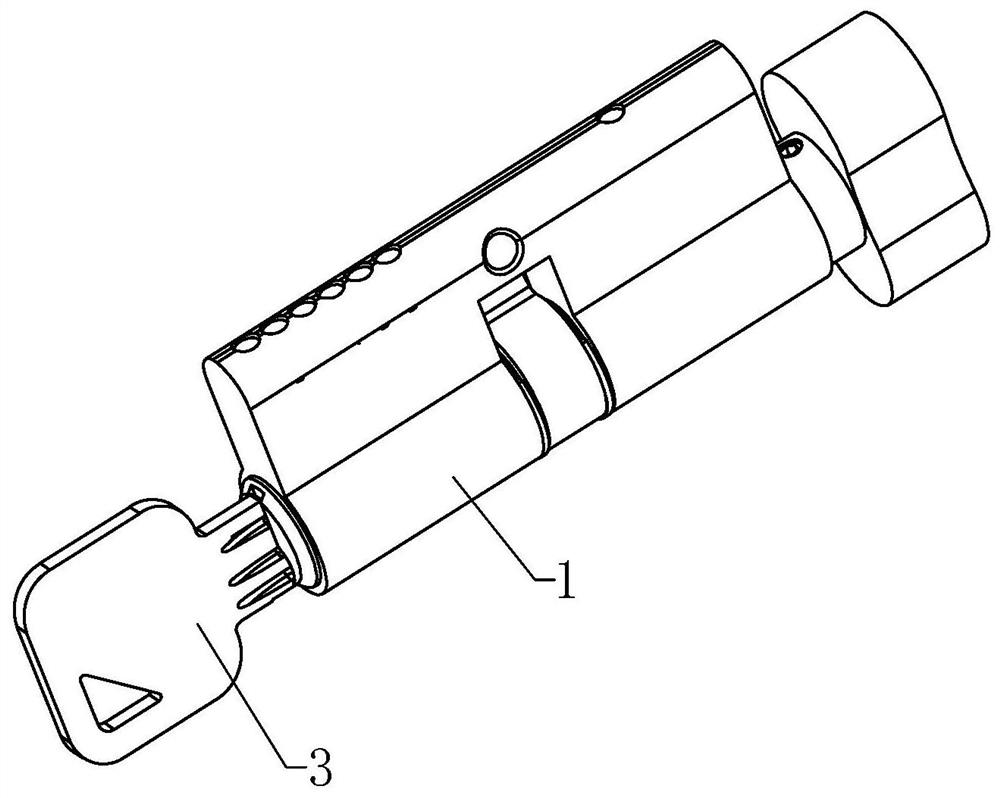
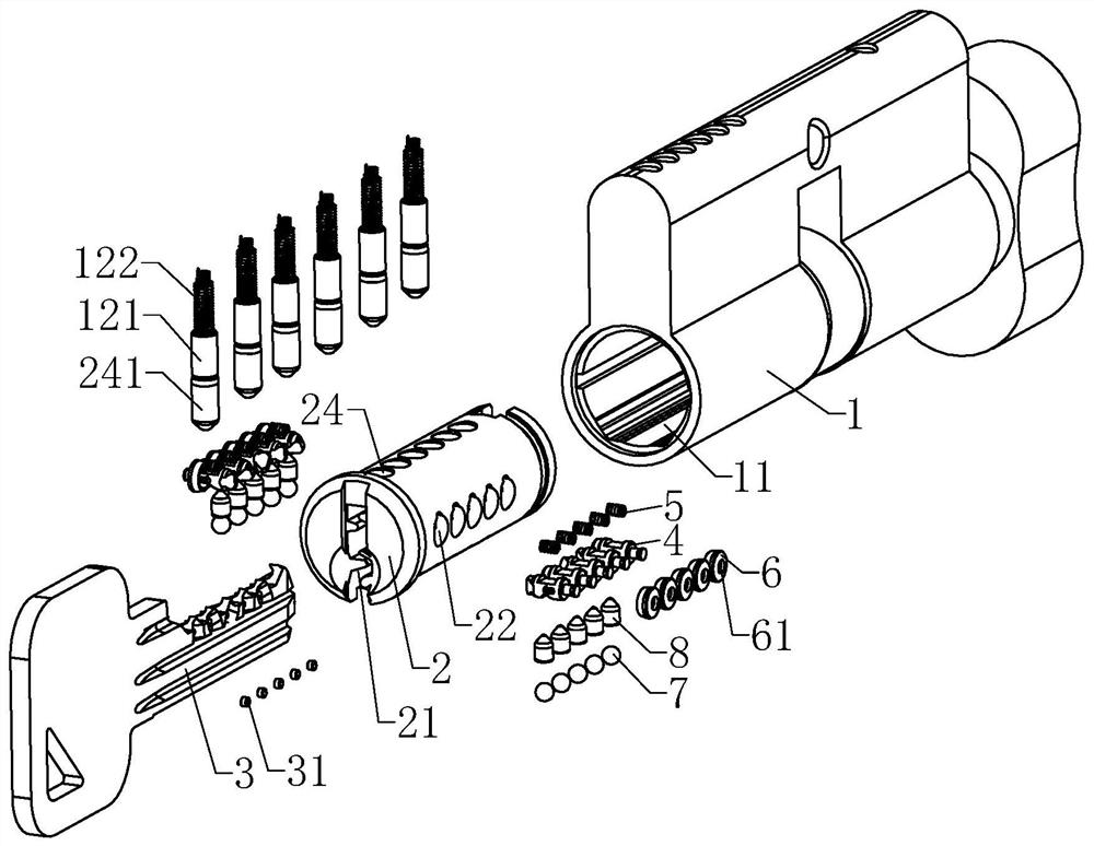
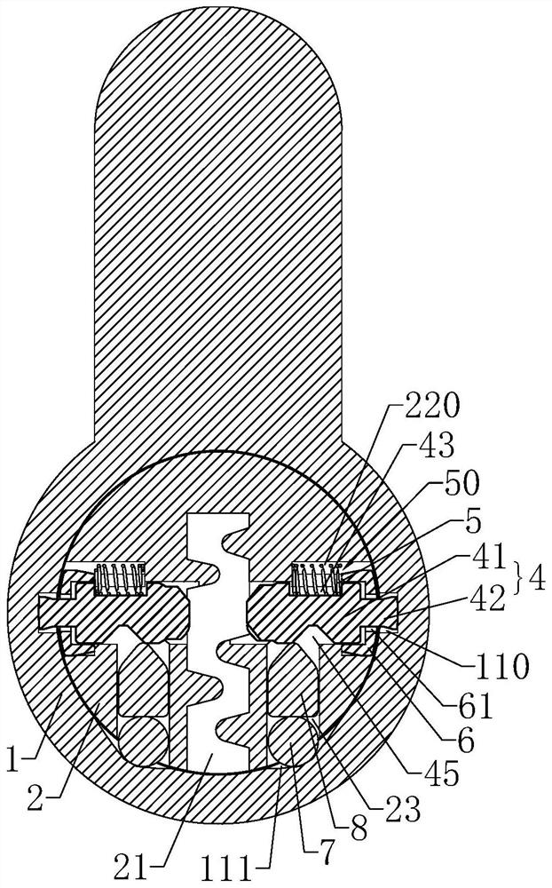
[0032] as attached Figures 1 to 4 And attached Figures 9 to 13 As shown, a magnetic lock cylinder includes a lock shell 1, and the lock shell 1 is provided with a lock cylinder hole 11, and a lock cylinder 2 is arranged to rotate in the lock cylinder hole 11, and the axial direction of the lock cylinder 2 is The key hole 21 for inserting the key 3 is provided in the direction, and the radial direction of the lock cylinder 2 is provided with a number of side bead holes 22 communicating with the key hole 21. The key 3 is provided with a number of 3. The tooth flower grooves 30 inclined at different angles or the same angle in the length direction. The side beads 4 that can be matched with the tooth flower grooves 30 are movably arranged in the side bead holes 22. Each of the side beads The head end of 4 has the same inclined portion...


PUM


Abstract

The invention discloses a magnetic lock cylinder. The magnetic lock cylinder comprises a lock shell. A lock core hole is formed in the lock shell. A lock core is rotatably arranged in the lock core hole. A key hole allowing a key to be inserted is formed in the lock core in the axial direction. A plurality of side bead holes communicated with the key hole are formed in the lock core in the radialdirection. The key is provided with a plurality of tooth grooves inclined at different angles or the same angle relative to the length direction of the key. Side beads capable of being matched with the tooth grooves in a one-to-one correspondence mode are movably arranged in the side bead holes, and an inclined part with the same inclination angle as the tooth groove correspondingly matched with the side bead is arranged at the head end of each side bead. A clamping groove is formed in the side wall of the lock core hole. First springs for driving the tail ends of the side beads to be clampedinto the clamping groove when the lock cylinder is in a locked state are arranged in the side bead holes. Magnetic beads are embedded into the key, and the magnetic force of the magnetic beads for adsorbing the side beads is larger than the elastic force of the first springs. The magnetic lock cylinder has higher safety coefficient, the key has a much larger keycode base, and technical opening oflawbreakers is more effectively prevented.

Description

【Technical field】 [0001] The invention relates to the technical field of locks, in particular to a magnetic lock cylinder. 【Background technique】 [0002] Generally, the existing lock cylinder is provided with a front pinball set and a side pinball set. When the correct key is inserted, the correct key pushes the front pinball set and the side pinball set to the unlocking position through the teeth, and then passes The key drives the lock cylinder to rotate to complete the unlocking. In the prior art, the tooth pattern on the key is generally a circular groove. After the key is inserted, the circular groove only needs to be in contact with the front marble group or the side marble group. The position of the lock is aligned, and the lock can be unlocked. This kind of lock cylinder is easy to be opened by criminals, and the safety factor is low, which is not conducive to the protection of the user's property safety; Increase the number of corrugations on the key, but due to t...

Claims


Application Information

Patent Timeline
Patent Type & Authority Applications(China)
IPC IPC(8): E05B27/00E05B47/00E05B15/00E05B15/14E05B19/06
CPCE05B27/0032E05B27/0007E05B27/0017E05B47/0045E05B19/0017
Inventor 曹小霞杨铭华李军
Owner ZHONGSHAN CITY JIXIN CORE LOCK CO LTD
Why Eureka
Try Eureka