
Display apparatus and control method thereof

A technology of a display device and a control method, which is applied in the direction of digital output to display devices, TVs, color TVs, etc., which can solve problems such as stuttering, insufficient algorithm time, and inability to display on the full screen, so as to ensure the algorithm time and meet the requirements of normal shooting Effect

Active Publication Date: 2021-02-19
YUNGU GUAN TECH CO LTD
View PDF11 Cites 2 Cited by
  • Summary
  • Abstract
  • Description
  • Claims
  • Application Information

AI Technical Summary

Problems solved by technology

[0005] However, the above-mentioned full-screen solution in the prior art cannot use the under-screen camera to take pictures or shoot videos without being affected by the screen in the normal preview display state. show
Especially in the state of collecting video, the conventional sampling frequency needs to be 30Hz (that is, 30 frames per second). If the frequency is too low, there will be a freeze phenomenon, and if the frequency is too high, the algorithm time will be insufficient.
Therefore, in the case of ensuring the video sampling frequency, it is also a technical problem to reserve enough algorithm time

Method used


Image

  • Display apparatus and control method thereof
  • Display apparatus and control method thereof
  • Display apparatus and control method thereof

Examples


Embodiment Construction

[0028] In order to have a further understanding of the purpose, structure, features, and functions of the present invention, the following detailed descriptions are provided in conjunction with the embodiments.

[0029] The display device of the present invention can be various electronic devices such as smart phones, tablet computers, televisions, monitors, and display screen modules.

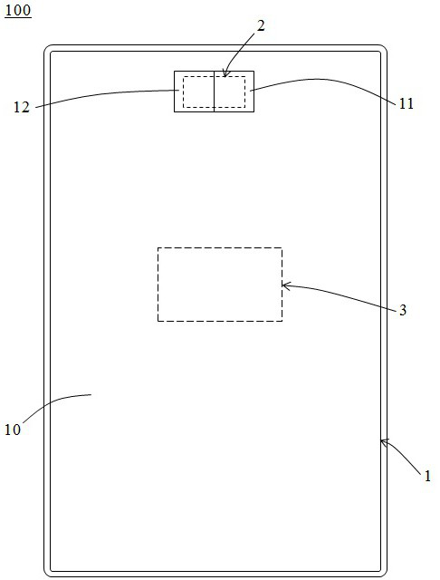
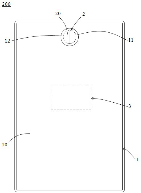
[0030] See figure 1 , figure 1 It is a schematic diagram of a display device 100 according to an embodiment of the present invention. A display device 100 provided by the present invention includes a display panel 1 , a camera module 2 and a control module 3 .

[0031] The display panel 1 includes a main screen area 10 , a first auxiliary screen area 11 and a second auxiliary screen area 12 , and the first auxiliary screen area 11 and the second auxiliary screen area 12 are connected to the main screen area 10 respectively. Preferably, the main screen area 10, the first auxiliary screen are...


PUM


Abstract

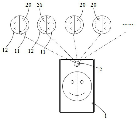
The invention provides a display apparatus and a control method thereof. The display apparatus comprises a display panel and a camera module. The display panel comprises a main screen area, a first auxiliary screen area and a second auxiliary screen area. The camera module is arranged below the display panel and corresponds to the first auxiliary screen area and the second auxiliary screen area inposition. The first auxiliary screen area and the second auxiliary screen area are controlled to be in a non-display state alternately at a preset time interval in the process of collecting images byusing the camera module; after the first auxiliary screen area is in a non-display state, the camera module is controlled to acquire images through the first auxiliary screen area, and the main screen area and the second auxiliary screen area are controlled to normally display the images acquired by the camera module; after the second auxiliary screen area is in the non-display state, the cameramodule is controlled to acquire images through the second auxiliary screen area, and the main screen area and the first auxiliary screen area are controlled to normally display the images acquired bythe camera module. According to the invention, the full screen can still synchronously and normally display an image when a under-screen camera device is used for collecting the image, and sufficientalgorithm time of the camera device can be ensured.

Description

technical field [0001] The present invention relates to the field of display technology, in particular to a display device and a control method thereof. Background technique [0002] In the field of electronic equipment terminals with display devices, currently the display panel pursues a screen-to-body ratio as large as possible to enhance user experience. For smartphones with a full-screen concept, various optical sensing elements such as front cameras, face recognition, and fingerprint recognition are expected to be integrated into the screen to achieve the "full-screen" effect that the screen occupies the entire front panel of the phone. [0003] One implementation method in the prior art is to arrange the above-mentioned optical sensing element (such as the front camera) under the display screen, and make slots or holes on the display screen corresponding to the position of the optical sensing device, but these The slotted or holed area cannot display the picture norma...

Claims


Application Information

Patent Timeline
Patent Type & Authority Applications(China)
IPC IPC(8): H04N5/232H04N5/225H04N5/262H04N5/265H04M1/02G06F3/14
CPCH04N5/2624H04N5/265H04M1/0264H04M1/0266G06F3/1431H04N23/57H04N23/60
Inventor 刘如胜葛泳李俊峰杜哲
Owner YUNGU GUAN TECH CO LTD
Learn More