Medical surgical rehabilitation bed

A rehabilitation bed and surgery technology, applied in the field of medical equipment, can solve the problems that rehabilitation personnel cannot independently control and toggle the bending bar for training, cannot meet the use requirements, and have single functions

Inactive Publication Date: 2021-02-23
杨志巧
View PDF10 Cites 0 Cited by
  • Summary
  • Abstract
  • Description
  • Claims
  • Application Information

AI Technical Summary

Problems solved by technology

[0003] The above-mentioned patent has a single function, and can only make the hip joint and knee joint move synchronously in a self-help way. In actual use scenarios, due to the different rehabilitation conditions of the rehabilitation personnel, it is necessary to carry out gradual and in-depth rehabilitation training for the rehabilitation personnel according to the situation. Rehabilitation training of multiple joints is carried out on a single joint, and some rehabilitation personnel cannot independently control and toggle the bending bar for training. The above patents cannot meet the actual use needs

Method used


Image

  • Medical surgical rehabilitation bed
  • Medical surgical rehabilitation bed
  • Medical surgical rehabilitation bed

Examples


Embodiment 1

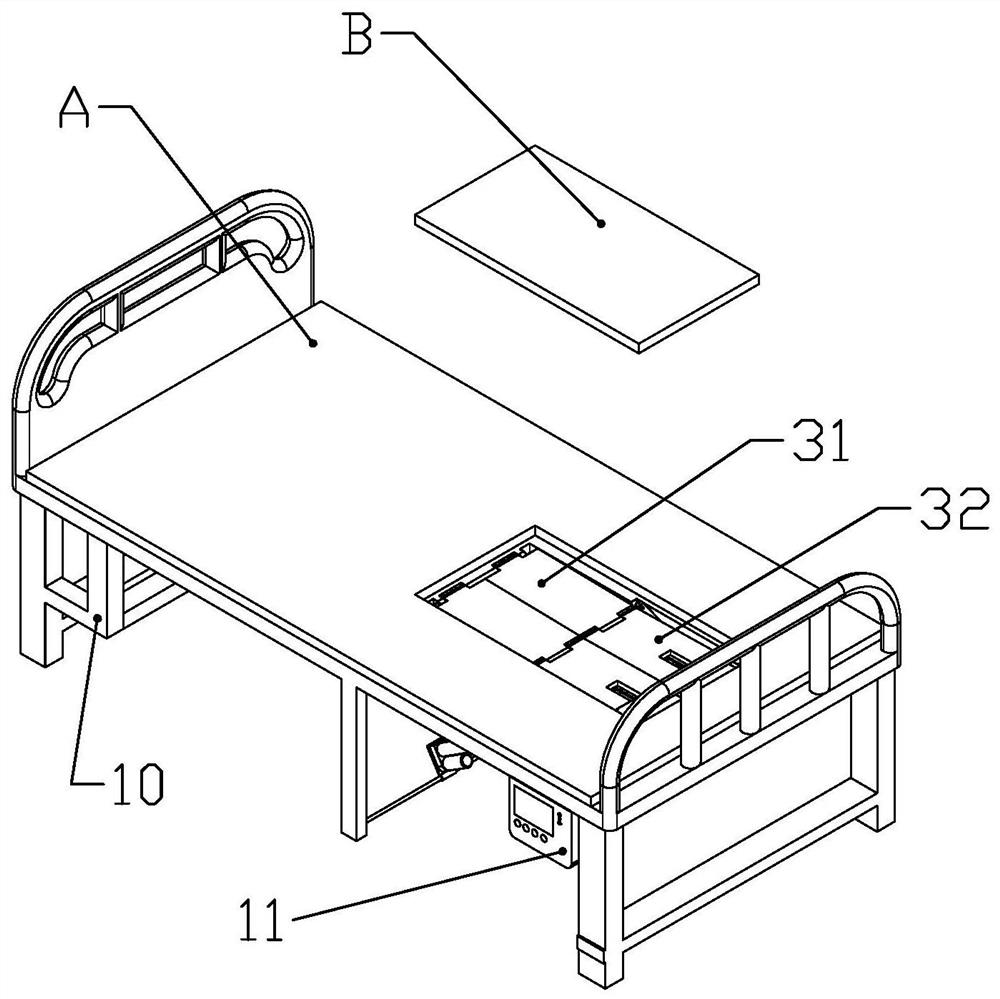
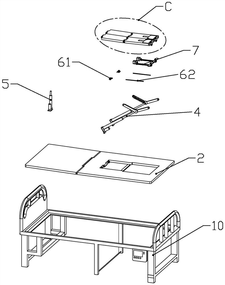
[0050]according toFigure 1 to Figure 15 As shown, the medical surveillance bed, including the bed frame 10, and a bed plate 2 mounted on the upper end of the bed frame 10; the rear of the bed 2 is rotated to have two symmetric settings. The shaft is provided in the left-right direction of the thigh support plate 31 for driving the thigh reciprocating motion; the rear end of the thigh support plate 31 is rotatably coupled to a calf support plate 32 provided with the rotating shaft in the left-right direction.

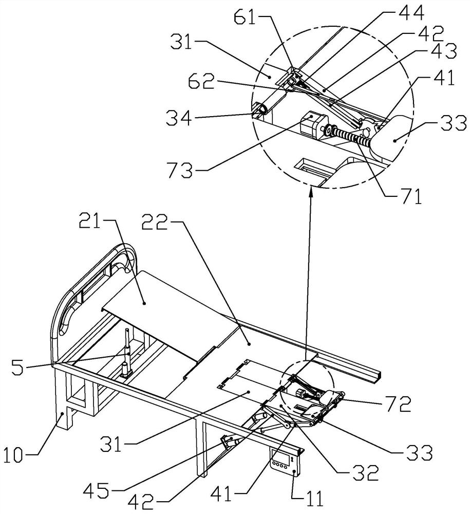
[0051]The rear end of each of the thigh support plates 31 is formed with a rotating tube A311 that is rotatably connected to the corresponding calf support plate 32 in the left-right direction; the front end of the respective papping support plates 32 is near the bed frame 10 Sliding is a stop casing 61 coaxial with the rotating tube A311 with the corresponding rotating tube A311.

[0052]The front ends of each of the calf support plates 32 are respectively formed with a rotating tu...

Embodiment 2

[0091]according toFigure 16 to Figure 17As shown, this embodiment makes the following improvements on the basis of Embodiment 1: Each of the second links 42 is slidably connected along the length of the corresponding second link 42 on the side facing the thigh support plate 31 There is a plug-in strip 43 that can be plugged into the first connecting rod 41; each of the second connecting rods 42 is slidably connected to the corresponding plug-in strip 43 along the axis of the rotating tube a311. The first connecting rod 41 slides the plug-in driving part 44.

[0092]The side of each second link 42 facing the thigh support plate 31 is formed with a sliding groove 421 slidably connected to the corresponding plug-in strip 43 along the length direction of the corresponding second link 42; each The sliding groove 421 is located on the two side walls of the corresponding plug-in strip 43 close to the outside and is formed with a limit strip 4211 that restricts the plug-in strip 43 from slidin...


PUM


Abstract

The invention discloses a medical surgical rehabilitation bed. The medical surgical rehabilitation bed comprises a bed frame and a bed board; the bed board is rotatably connected with two thigh supporting plates; each thigh supporting plate is rotationally connected with a shank supporting plate; a rotating pipe a is formed on each thigh supporting plate; each shank supporting plate is connected with a stop casing pipe in a sliding manner; the lower end of the bed board is provided with leg driving assemblies; each leg driving assembly includes a first connecting rod, a second connecting rod and a rotating push rod; non-connected ends of the first connecting rod and the second connecting rod are rotationally connected with the tail end of a rod body of the corresponding rotating push rod;and a thigh supporting plate supporting strip is formed at the lower end of the bed board. The medical surgical rehabilitation bed has a hip joint rehabilitation function, and the rotating push rods extend and retract in a reciprocating manner to drive hip joints to be trained; the medical surgical rehabilitation bed has a knee joint rehabilitation function, and the rotating push rods extend and retract in a reciprocating manner to drive knee joints to exercise; the medical surgical rehabilitation bed has an ankle joint rehabilitation function, and a driving motor drives both legs to bend andstretch in a reciprocating manner, so that the hip joints, the knee joints and the ankle joints can exercise; and the medical surgical rehabilitation bed employs an automatic process, and is simple tooperate, and convenient to use.

Description

Technical field[0001]The present invention belongs to the technical field of medical equipment, and in particular to a medical examination bed.Background technique[0002]The Chinese Patent Document of the Document No. CN206443845U disclosed a self-catering passive knee rehabilitation training bed involving a medical rehabilitation device, which is made of a bed, a thigh housing, a calf fixture, a link and a plurality of bending lever. The body is composed of a bed frame, a bed, and a lower bed; the lower bed is provided with two parallel slots, and each groove is provided with a symmetrical thigh holder, and the calf fixation with the thigh fixed rod hinges. The rod, the other end of the thigh holder is hinged, and the other end of the slot rail is provided with a roller, the roller is from the bottom surface of the tank rail; one end of the link is hinged by the connecting rod and the calf fixtures. The other end is hinged to the lower end of the dial bending rod; the pair of dial b...

Claims


Application Information

Patent Timeline
IPC IPC(8): A61H1/02
CPCA61H1/0255A61H1/0266A61H2201/0142A61H2201/1207A61H2201/5035A61H2201/14
Inventor 杨志巧
Owner 杨志巧
Why Eureka
Try Eureka