Dual-unit step-up switch converter

A boosted, soft-switching technology, applied in the conversion equipment with intermediate conversion to AC, DC power input converted to DC power output, instruments, etc., can solve the problems of loss and increase in loss, etc.

Inactive Publication Date: 2003-10-08
EMERSON NETWORK POWER CO LTD
View PDF1 Cites 1 Cited by
  • Summary
  • Abstract
  • Description
  • Claims
  • Application Information

AI Technical Summary

Problems solved by technology

However, the auxiliary switch Sa is hard turned off, so there is a ...

Method used


Image

  • Dual-unit step-up switch converter
  • Dual-unit step-up switch converter
  • Dual-unit step-up switch converter

Examples


Embodiment Construction

[0019] The present invention will be further described in detail below through specific embodiments in conjunction with the accompanying drawings.

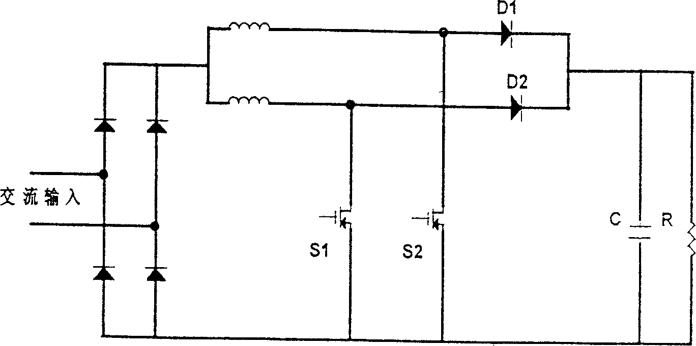
[0020] see Figure 6 , The shown dual-unit boost soft switching converter includes a first main power switch S1, a second main power switch S2, a first inductor L1, an energy storage inductor Lf, first and second diodes D1, D2, and a first auxiliary diode Da, the second auxiliary diode Db, the resonant inductor Lr, the third auxiliary diode Da3 and the auxiliary switch Sa. The first and second main power switches S1 and S2 are connected across the positive and negative ends of the DC bus, and the energy storage inductor Lf is in series Connected between the input end of the positive end of the DC bus and the first main power switch S1, the first inductor L1 is connected in series between the first and second main power switches S1 and S2 at the positive end of the DC bus, and the second diode D2 is connected in series Between the seco...


PUM


Abstract

A dual-unit step-up type soft switch converter is composed of two powr diodes, two resonance circuits, and an auxilairy switch. The soft cut-off of auxiliary switch, the soft on-off of power diode and zero-current cut-off of output rectifying diode are realized on the basis that two resonance capacitors whose voltage can not change suddenly and used.

Description

Technical field [0001] The invention relates to a double-unit boost type soft switching converter. Background technique [0002] For single-phase power factor correction circuits, people have carried out a lot of research in recent years and proposed many power factor correction circuits. Among them, the most researched is the boost power factor correction circuit. For example, document [1]: Chinese Patent CN98113189.1 "One A Kind of Soft Switching Topology Circuit"; Literature [2]: B. Miwa, D. Otthe, and M. Schlecht, "High efficiency power factor correction using interleaving techniques," in Apec'92, pp.557-568; Literature [3] Henrique ACBraga and Ivo Barbi, "A3-kW unity-power-factor rectifierbased on a two-cell boost converter using a new parallel-connectiontechnique," in IEEE Trans.on Power Elec., vol.14, no.1, pp .653-661, Jan. 1999; Literature [4] MSVilela, EAAColelho, JBVieira Jr., LCde Freitasand VJFarias, "A family of soft-switching converters with low stress of voltage a...

Claims


Application Information

Patent Timeline
IPC IPC(8): H02M3/22H02M3/28
CPCY02B70/1491Y02B70/10
Inventor 史立生
Owner EMERSON NETWORK POWER CO LTD
Why Eureka
Try Eureka