Power factor corrector realized in an intelligent embedded way and control method thereof

A technology of power factor correction and control method, which is applied in the direction of control/regulation system, output power conversion device, DC power input conversion to DC power output, etc., and can solve problems such as large number of components, single function, complex circuit structure, etc. , to simplify the circuit structure, simplify the processing process, and realize the effect of over-current protection

Active Publication Date: 2014-08-20
深圳市益力盛电子有限公司
View PDF6 Cites 0 Cited by
  • Summary
  • Abstract
  • Description
  • Claims
  • Application Information

AI Technical Summary

Problems solved by technology

[0005] In order to avoid the deficiencies of the prior art, the present invention proposes an intelligent embedded power factor corrector and its control method, which solves the problems of complex circuit structure, large number of components and single function in the prior art, and improves Practical performance

Method used


Image

  • Power factor corrector realized in an intelligent embedded way and control method thereof
  • Power factor corrector realized in an intelligent embedded way and control method thereof
  • Power factor corrector realized in an intelligent embedded way and control method thereof

Examples


Embodiment Construction

[0025] Now in conjunction with embodiment, accompanying drawing, the present invention will be further described:

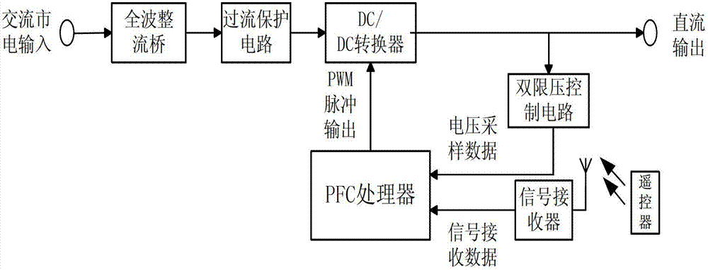
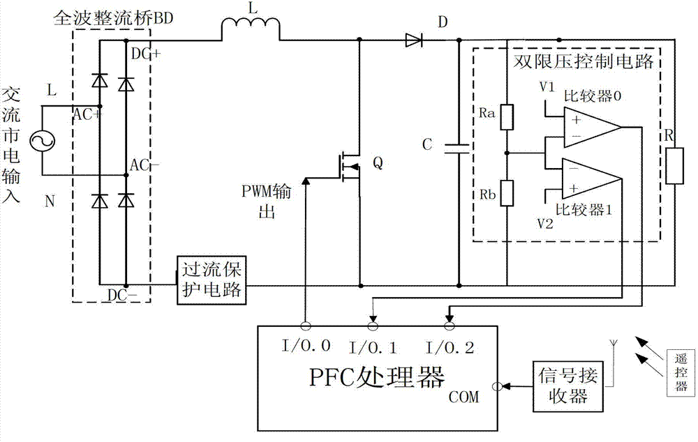
[0026] see image 3 According to the concept of this case and the implementation examples based on the BOOST step-up converter, it mainly includes AC mains input, full-wave rectifier bridge BD, overcurrent protection circuit, dual voltage limit control circuit, inductor L, power switch tube Q, diode D, capacitor C, load resistor R and PFC processor. The live line L of the mains is connected to the AC input terminal AC+ of the rectifier bridge BD; the neutral line N of the mains is connected to the AC- terminal of the rectifier circuit; one end of the inductor L is connected to the DC input terminal DC+ of the rectifier bridge BD, and the other end is connected to the power The drain of the switch tube Q is connected to the anode of the diode D; the source of the switch tube Q is connected to one end of the overcurrent protection circuit, and the gate of the swit...


PUM


Abstract

The invention relates to a power factor corrector realized in an intelligent embedded way and a control method thereof. The power factor corrector comprises a PFC (Power Factor Correction) processor with an embedded chip as core, a full wave rectifying circuit, an overcurrent protection circuit, a double-limiting voltage control circuit, a DC / DC (Direct Current / Direct Current) conversion circuit, an inductor L, a diode D, a capacitor C and a power switch tube Q. The power factor corrector realized in the intelligent embedded way, provided by the invention, has the advantages as follows: 1) duty cycle is directly stored in a chip in the form of data so as to output a PWM (Pulse Width Modulation) control wave, so that the traditional feedback circuit method is saved, a circuit structure is simplified, the usage of components is reduced and the processing process is simple and convenient; 2) the processor can be used for adjusting programs according to actual requirements in real time without frequently modifying hardware; 3) a voltage constant output function is achieved and load requirements are satisfied; 4) a remote control voltage regulating function is achieved, so that greater convenience for user in use is achieved; 5) soft startup and soft shutdown of a circuit are achieved and a circuit component is protected; and 6) overcurrent protection is achieved so that the safety of the circuit is ensured.

Description

technical field [0001] The invention belongs to the circuit topology of a power factor correction (PFC) device and a control method thereof, in particular to a power factor correction (PFC) device and a control method realized by an intelligent embedded system. Background technique [0002] One of the main development trends of modern power supplies is to improve the power factor at the input end of the AC / DC converter and reduce the harmonic pollution to the power grid. At present, there are many control methods of power factor correction (PFC) researched and applied, such as the new digital control power supply PFC circuit with patent application number 200920175503.7, which realizes the circuit as figure 1 shown. It is characterized in that it includes an input circuit and an output circuit, a two-phase interactive BOOST topology converter is arranged between the input circuit and the output circuit, the output circuit is connected to a DSP processor through a feedback c...

Claims


Application Information

Patent Timeline
Patent Type & Authority Patents(China)
IPC IPC(8): H02M1/42H02M3/156H02H3/08
CPCY02B70/126Y02B70/10
Inventor 贺宏锟石雷王林博阳金金
Owner 深圳市益力盛电子有限公司
Why Eureka
Try Eureka