Non-damping winding permanent-magnet synchronous motor grid connection method

A permanent magnet synchronous, non-damping technology, applied in the field of motor grid connection, can solve the problems of not having the power frequency operation ability of the grid, and achieve the effect of saving the capacity of the inverter, expanding the application field, and high success rate

Active Publication Date: 2014-11-19
中安星瑞航空科技有限公司
View PDF6 Cites 8 Cited by
  • Summary
  • Abstract
  • Description
  • Claims
  • Application Information

AI Technical Summary

Problems solved by technology

[0005] The purpose of the present invention is to solve the problem that the non-damping winding permanent magnet synchronous motor can only be used in frequency conversion and speed regulation occasions, but does not have the power frequency operation capability of the power grid, and provides a non-damping winding permanent magnet synchronous motor grid-connected method

Method used


Image

  • Non-damping winding permanent-magnet synchronous motor grid connection method
  • Non-damping winding permanent-magnet synchronous motor grid connection method
  • Non-damping winding permanent-magnet synchronous motor grid connection method

Examples


specific Embodiment approach 1

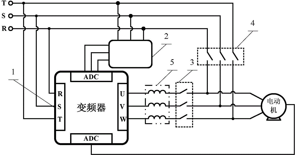
[0035] Specific implementation mode one: the following combination Figure 1 to Figure 7 Describe this embodiment, the grid connection method of permanent magnet synchronous motor with no damping winding described in this embodiment, the grid connection method is realized based on the frequency converter 1, the voltage acquisition board 2, the first contactor 3 and the second contactor 4,

[0036] The voltage acquisition board 2 is used to collect the frequency, amplitude and phase of the grid voltage, and provide it to the frequency converter 1. The three-phase incoming lines R, S, and T of the grid are connected to the permanent magnet synchronous motor with no damping winding in two ways. The first The first road is connected to the permanent magnet synchronous motor without damping winding through the frequency converter 1 and the first contactor 3 in turn, and the second road is connected to the permanent magnet synchronous motor without damping winding through the second ...

specific Embodiment approach 2

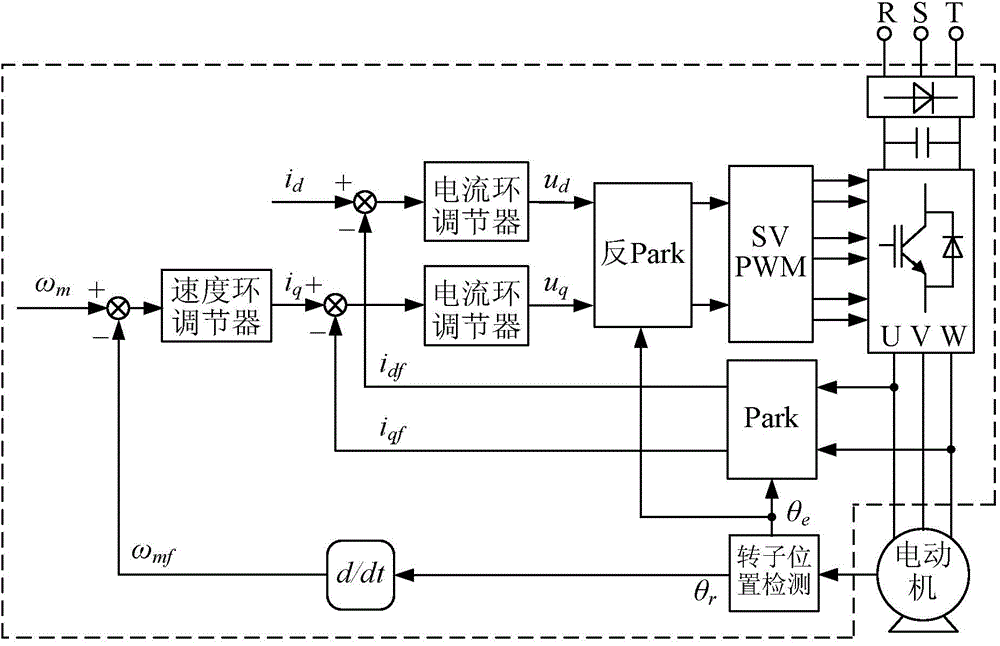
[0042] Specific implementation mode two: the following combination Figure 7 This embodiment will be described. This embodiment will further explain Embodiment 1. The method for switching a permanent magnet synchronous motor with no damping winding from the power grid operation state to the inverter 1 operation state is as follows:

[0043] First, through the control of the frequency converter 1, the opening time of the second contactor 4 is earlier than the closing time of the first contactor 3, and then the rotor position of the permanent magnet synchronous motor with no damping winding is tracked online, and the rotor position information is provided to the frequency converter 1, The frequency converter 1 is started to run, thereby realizing the switching of the non-damping winding permanent magnet synchronous motor from the power grid operation state to the operation state of the frequency converter 1 .

[0044] In the operation process of this embodiment, the contactor is...

specific Embodiment approach 3

[0047] Specific implementation mode three: the following combination Figure 1 to Figure 7 Describe this embodiment, the grid connection method of permanent magnet synchronous motor with no damping winding in this embodiment, the grid connection method is based on frequency converter 1, voltage acquisition board 2, first contactor 3, second contactor 4 and reactor 5 achieved,

[0048] The voltage acquisition board 2 is used to collect the frequency, amplitude and phase of the grid voltage, and provide it to the frequency converter 1. The three-phase incoming lines R, S, and T of the grid are connected to the permanent magnet synchronous motor with no damping winding in two ways. The first The first road is connected to the permanent magnet synchronous motor without damping winding through the frequency converter 1, the reactor 5 and the first contactor 3 in turn, and the second road is connected to the permanent magnet synchronous motor without damping winding through the seco...


PUM


Abstract

The invention discloses a non-damping winding permanent-magnet synchronous motor grid connection method and belongs to the technical field of motor grid connection. The method aims to solve the problems that a non-damping winding permanent-magnet synchronous motor can be only used on a variable-frequency speed control occasion and does not have the power frequency operating capacity of a power grid. According to the method, the non-damping winding permanent-magnet synchronous motor is soft started under the control of a frequency converter, and then, the frequency converter is regulated, wherein firstly, the fundamental frequency of the voltage of the output end of the frequency converter is made to be consistent with the frequency of a power grid; secondly, the difference between the fundamental amplitude of the voltage of the output end of the frequency converter and the voltage amplitude of the power grid is made to be within a preset threshold range; finally, the fundamental phase of the voltage of the output end of the frequency converter is made to be consistent with the phase of the voltage of the power grid; next, the switch-on time moment of a second contact is made to be later than the switch-off time moment of a first contact under the control of the frequency converter, and the operating state that the non-damping winding permanent-magnet synchronous motor is soft started is switch to the power grid operating state. The non-damping winding permanent-magnet synchronous motor grid connection method is used for grid connection of the non-damping winding permanent-magnet synchronous motor.

Description

technical field [0001] The invention relates to a grid connection method for a permanent magnet synchronous motor with no damping winding, and belongs to the technical field of motor grid connection. Background technique [0002] At present, there are two main operating modes of the electric drive system driven by the motor, namely, the speed-regulating system mainly based on the frequency conversion control mode and the non-speed-adjusting system mainly based on the grid power frequency operation. Among them, the latter is still widely used due to its advantages of low system cost, high reliability, simple control, and high full-load efficiency. [0003] Motors conventionally used for power frequency operation mainly include asynchronous motors, electric excitation synchronous motors, and permanent magnet synchronous motors with damping windings on the rotor. The permanent magnet synchronous motor with no damping winding on the rotor, because it cannot generate asynchronou...

Claims


Application Information

Patent Timeline
Patent Type & Authority Applications(China)
IPC IPC(8): H02J3/40
Inventor 徐殿国倪荣刚王高林张国强贵献国
Owner 中安星瑞航空科技有限公司
Why Eureka
Try Eureka