Three-phase asynchronous motor electric-braking device and control method thereof

An electrical braking, three-phase asynchronous technology, applied in the deceleration device of the AC motor, the starter of a single polyphase induction motor, the motor generator/starter, etc. torque, poor braking accuracy, etc., to achieve the effect of soft start, small braking impact, and rapid braking

Active Publication Date: 2013-01-16
ZHUZHOU NAT ENG RES CENT OF CONVERTERS
View PDF6 Cites 9 Cited by
  • Summary
  • Abstract
  • Description
  • Claims
  • Application Information

AI Technical Summary

Problems solved by technology

[0011] The braking device and braking method used for motor braking in Document 2 adopts super capacitor DC energy-consuming braking technology, which requires a set of DC power supply device, and the equipment cost is high
In addition, when some drag systems use energy-consumption braking to stop, on the one hand, it needs to consider the need for a large braking torque, and on the other hand, it is not possible to overheat the winding due to the excessive current of the stator and rotor circuits. Due to the limitations of the motor, the braking accuracy is relatively poor, and the braking effect is also different due to the different motor power.

Method used


Image

  • Three-phase asynchronous motor electric-braking device and control method thereof
  • Three-phase asynchronous motor electric-braking device and control method thereof
  • Three-phase asynchronous motor electric-braking device and control method thereof

Examples


Embodiment Construction

[0036] The following will clearly and completely describe the technical solutions in the embodiments of the present invention with reference to the accompanying drawings in the embodiments of the present invention. Obviously, the described embodiments are only part of the embodiments of the present invention, not all of them. Based on the embodiments of the present invention, all other embodiments obtained by persons of ordinary skill in the art without creative efforts fall within the protection scope of the present invention.

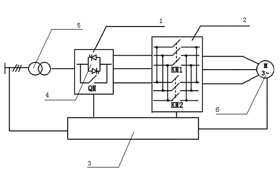
[0037] as attached image 3 As shown, a specific embodiment of a three-phase asynchronous motor electric braking device and its control method according to the present invention is given, and the present invention will be further described below in conjunction with the accompanying drawings and specific embodiments.

[0038] The present invention proposes a simple structure, safe and reliable electrical brake device for three-phase asynchronous motors...


PUM


Abstract

The invention discloses a three-phase asynchronous motor electric-braking device and a control method thereof. The three-phase asynchronous motor electric-braking device comprises a thyristor voltage regulator, a braking actuator and a control and status monitor. The thyristor voltage regulator is connected with a brake actuator and a three-phase alternating-current power source, the braking actuator is connected with a motor, and the control and status monitor is connected with the braking actuator, the three-phase alternating-current power source and the motor respectively. Besides, the thyristor voltage regulator comprises a bypass contactor and at least one thyristor valve group which are in parallel connection. The braking actuator comprises a forward contactor and a reverse contactor which are in parallel connection. The control and status monitor changes input voltage of the stator of the motor by controlling the thyristor valve group. The electric-braking device is simple in structure, reliable and safe in performance and applicable to quick, accurate and smooth brake stop in a three-phase asynchronous motor driving system.

Description

technical field [0001] The invention relates to a motor braking device and a control method thereof, in particular to an electric braking device applied to a three-phase asynchronous motor and a control method thereof. Background technique [0002] Braking is one of the important issues in the electric drive system. In order to improve efficiency in industrial production, or in special applications such as fire protection, many machines require fast braking to achieve fast braking and accurate parking. There are two types of braking methods: mechanical braking and electrical braking. Mechanical braking mainly achieves the purpose of braking by increasing friction. It has disadvantages such as inconvenient operation, poor reliability, and complicated processing technology, and often fails to meet the requirements of use, while electrical braking overcomes the above shortcomings. Electric braking, also known as electromagnetic braking, causes the motor to generate an electrom...

Claims


Application Information

Patent Timeline
Patent Type & Authority Applications(China)
IPC IPC(8): H02P3/20H02P1/28
Inventor 彭勃林丽张铁军陈刚张少云曹洋雷立叶春明陈雪彭京刘斐
Owner ZHUZHOU NAT ENG RES CENT OF CONVERTERS
Why Eureka
Try Eureka