Starting circuit of band-gap reference source

A reference source circuit and start-up circuit technology, applied in the direction of adjusting electrical variables, control/regulation systems, instruments, etc., can solve the problems of increasing the area occupied by the layout, output voltage overshoot, etc.

Active Publication Date: 2019-12-13
SHANGHAI HUAHONG GRACE SEMICON MFG CORP
View PDF11 Cites 7 Cited by
  • Summary
  • Abstract
  • Description
  • Claims
  • Application Information

AI Technical Summary

Problems solved by technology

When the power supply is powered on, at the initial stage, because the circuit is not working, the node NST is at a low level, the PMOS transistors P6 and P7 are turned on, the node NST1 is charged to a high level, the NMOS transistor N2 is turned on, and the node PBIAS is pulled down, and the PMOS transistor P1 , P2, P3, P4 and P5 are turned on, so that there will be current poured into the main circuit of the bandgap reference, the loop operation reaches a stable point, and the bandgap reference circuit is established; when the bandgap reference circuit is established, the mirror current of the PMOS transistor P1 It flows to the resistor RST to generate a voltage NST. When the node NST voltage reaches the turn-on voltage of the NMOS transistor N1, N1 is turned on, P6 and P7 are weakly turned on, the node NST1 is pulled down, the NMOS transistor N2 is turned off, and the startup process ends; When the power is turned on in the order of seconds, due to the strong pull of the node PBIAS, the startup circuit will cause an overshoot of the output voltage. Generally, the solution to the overshoot is to hang a few pF or even more capacitors on the output, which will increase the occupation of the layout. area

Method used


Image

  • Starting circuit of band-gap reference source
  • Starting circuit of band-gap reference source
  • Starting circuit of band-gap reference source

Examples


Embodiment Construction

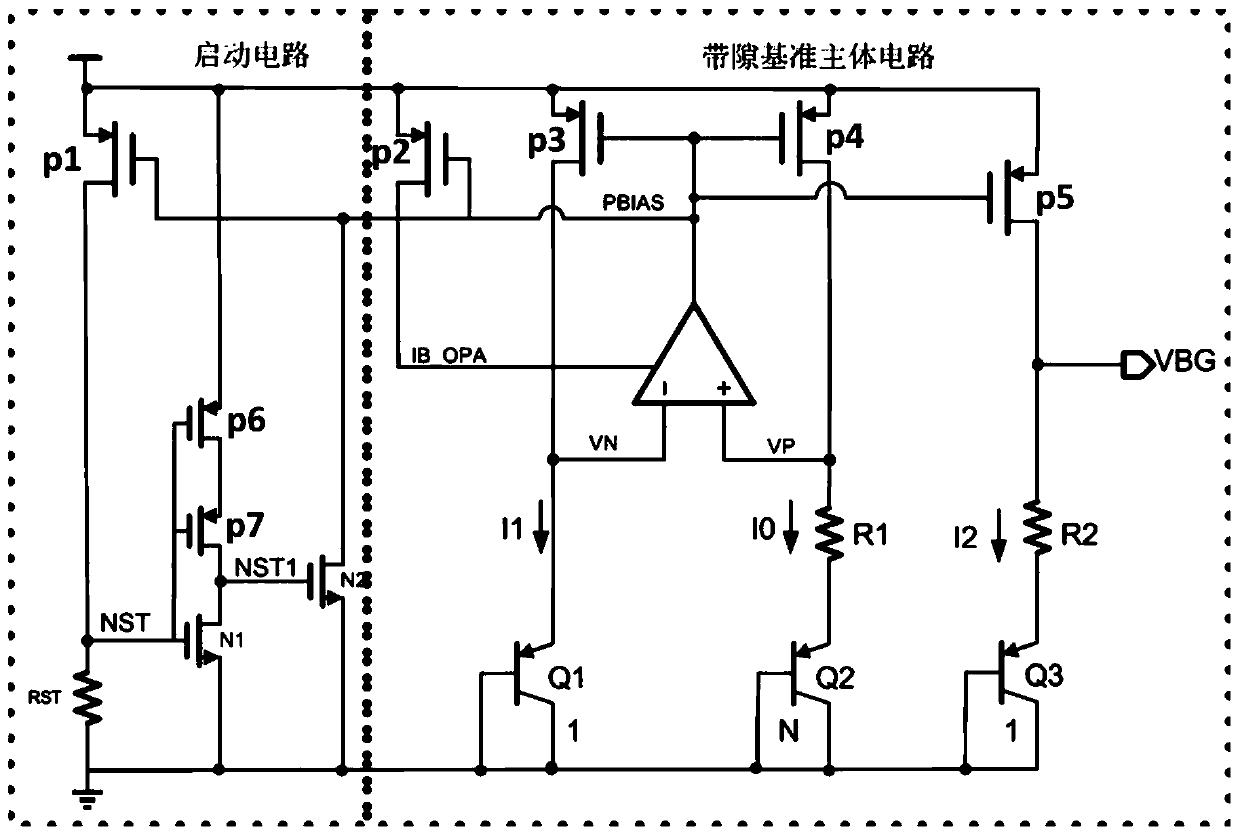
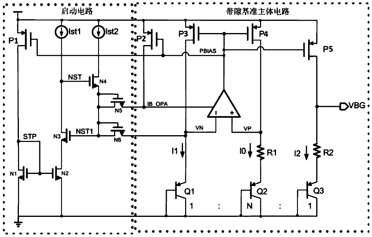
[0023] The starting circuit of the bandgap reference source of the present invention, such as figure 2 As shown, the bandgap reference source circuit includes a bandgap reference source main circuit and a start-up circuit; the start-up circuit provides start-up current for the main body circuit of the bandgap reference source:

[0024] The start-up circuit includes a first PMOS transistor (P1) and six NMOS transistors (N1-N6).

[0025] The source of the first PMOS transistor is connected to the power supply, and the drain is connected to the drain of the first NMOS.

[0026] The gate of the first NMOS is connected to the gate of the second NMOS and is short-circuited to the drain of the first NMOS, and the sources of the first NMOS and the second NMOS are grounded.

[0027] The drain of the second NMOS is connected to the source of the third NMOS.

[0028] The drain of the third NMOS is connected to the first starting current Ist1, the drain of the fourth NMOS is connected ...


PUM


Abstract

The invention discloses a band-gap reference source circuit. The band-gap reference source circuit comprises a band-gap reference source main body circuit and a starting circuit. The starting circuitprovides starting current for a main circuit of the band-gap reference source. The starting circuit comprises a first starting current and a second starting current, the starting currents are generally generated by a current bias circuit, the starting circuit can be completely switched off, no leakage current exists, and the precision of the output voltage of the band-gap reference source circuitis not affected. The circuit provided by the invention has the advantages that the soft start of the circuit can be achieved and the output voltage does not overshoot.

Description

technical field [0001] The invention relates to the field of semiconductor integrated circuits, in particular to a starting circuit of a bandgap reference source. Background technique [0002] The bandgap reference source circuit (BGR) is widely used in integrated circuits. The bandgap reference source usually provides stable reference voltage and reference current for other modules. It usually needs to start working with the establishment of the power supply, and it is not expected to see A bandgap reference circuit with overshoot usually consists of a start-up circuit and a main body circuit of the bandgap reference. figure 1 It is a basic bandgap reference source circuit. The dotted line box on the left in the figure is the startup circuit, and the dotted line box on the right side is the main circuit of the bandgap reference source. [0003] figure 1 The start-up circuit and the main circuit of the bandgap reference source circuit shown in are composed of multiple PMOS...

Claims


Application Information

Patent Timeline
Patent Type & Authority Applications(China)
IPC IPC(8): G05F1/625
CPCG05F1/625
Inventor 周宁
Owner SHANGHAI HUAHONG GRACE SEMICON MFG CORP
Why Eureka
Try Eureka