Passive and nondestructive clamping single-phase high-gain converter

A high-gain, converter technology, applied in the direction of conversion equipment without intermediate conversion to AC, can solve the problems of large voltage stress of the power switch tube, reduce the voltage stress of the power switch tube, and cannot achieve high-gain conversion, so as to reduce the voltage The effect of stress, easy control and simple structure

Active Publication Date: 2012-07-25
杭州浙阳电气有限公司
View PDF0 Cites 0 Cited by
  • Summary
  • Abstract
  • Description
  • Claims
  • Application Information

AI Technical Summary

Problems solved by technology

[0004] The present invention solves the problem that the voltage stress of the power switch tube of the conventional single-phase single-tube step-up DC-DC converter is relatively large and cannot realize high-gain conversion, and provides a method that can reduce the voltage stress of the power switch tube and realize high-gain conversion. Passive Lossless Clamp Single-Phase High-Gain Converter with Gain Conversion

Method used


Image

  • Passive and nondestructive clamping single-phase high-gain converter
  • Passive and nondestructive clamping single-phase high-gain converter
  • Passive and nondestructive clamping single-phase high-gain converter

Examples


Embodiment 1

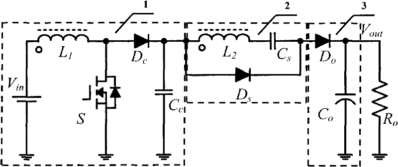
[0020] see figure 1 , a passive lossless clamping single-phase high-gain converter, including a single-phase Boost circuit unit 1, a voltage doubler circuit unit 2 and an output circuit unit 3 connected in series in sequence, and the single-phase Boost circuit unit 1 includes a coupling Inductor first winding L 1 , the coupled inductor first winding L 1 The first terminal of is connected to the positive pole of the power supply Vin, and the first winding L 1 The second end of the power switch tube S is connected to the drain of the power switch S and the anode of the clamp diode Dc, the cathode of the clamp diode Dc is connected to the first end of the clamp capacitor Cc, the source of the power switch tube S and the anode of the clamp diode Dc are connected to each other. The negative pole of the power supply Vin is connected;

[0021] The voltage doubling circuit unit 2 includes a coupled inductor second winding L 2 , the coupled inductor second winding L 2 One end is c...

Embodiment 2

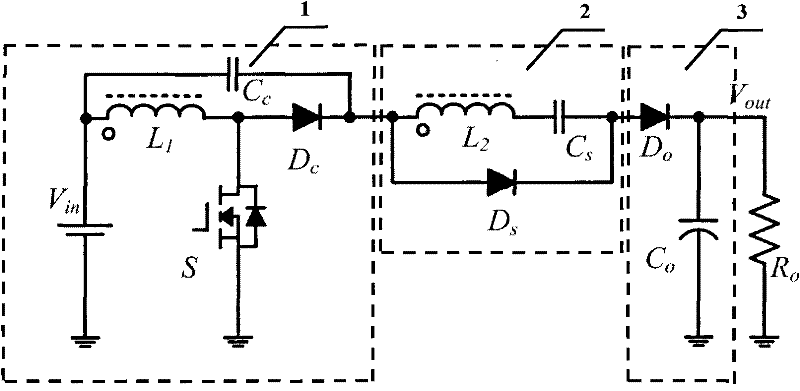
[0037] see figure 2 The difference between this embodiment and the first embodiment is that the second end of the clamping capacitor Cc is connected to the positive pole of the power supply Vin. All the other functions and structures are the same.

[0038] Embodiment two

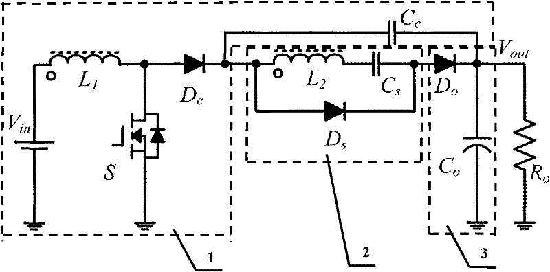
[0039] see image 3 The difference between this embodiment and Embodiment 1 and Embodiment 2 lies in that the second end of the clamping capacitor Cc is connected to the first end of the output capacitor Co. All the other functions and structures are the same.


PUM


Abstract

The invention discloses a passive and nondestructive clamping single-phase high-gain converter, which comprises a coupling inductor. The first end of a first winding of the coupling inductor is connected with the anode of a power supply; the second end of the first winding is connected with the drain electrode of a power switch tube and the anode of a clamping diode; the cathode of the clamping diode is connected with the first end of a clamping capacitor; the source electrode of the power switch tube is connected with the cathode of the power supply; one end of a second winding of the coupling inductor is connected with the anode of a fly-wheel diode and the cathode of the clamping diode; the second end of the second winding is connected with the first end of a double-voltage capacitor; the second end of the double-voltage capacitor is connected with the cathode of the fly-wheel diode; the first end of the second winding of the coupling inductor and the first end of the first windingof the coupling inductor serve as same name ends of the coupling inductor; the anode of an output diode is connected with the cathode of the fly-wheel diode; the cathode of the output diode is connected with the first end of an output capacitor; and the second end of the output capacitor is connected with the cathode of the power supply.

Description

technical field [0001] The invention relates to a DC-DC converter. Background technique [0002] In the solar power generation system, since the output voltage of a single solar cell is low, and the voltage required for inverter grid-connected power generation is relatively high, a first-stage DC-DC converter is required to convert low-voltage DC power into a high voltage suitable for grid-connected power generation. Voltage DC. In the distributed solar power generation scheme, the power capacity of a single solar cell is small, but the requirement for efficiency is high. [0003] The voltage gain of a conventional single-phase single-transistor boost (Boost) DC-DC converter is only determined by the duty cycle. The voltage gain is limited, and it is difficult to meet the conversion requirements of high gain. The voltage stress of the power switching tube is relatively large, and it is difficult to reduce the conduction loss by using a low-voltage high-performance switchin...

Claims


Application Information

Patent Timeline
Patent Type & Authority Patents(China)
IPC IPC(8): H02M3/06
Inventor 李武华赵一梅烨吕晓东何湘宁
Owner 杭州浙阳电气有限公司
Why Eureka
Try Eureka