Current continuous type high-gain DC-DC converter circuit

A DC-DC, continuous technology, applied in the field of current continuous high-gain DC-DC converter circuits, can solve the problems of large starting inrush current, discontinuous power supply current, output and input are not common, etc., to achieve voltage stress Reduced, improved reliability, high voltage gain effects

Active Publication Date: 2014-08-27
SOUTH CHINA UNIV OF TECH
View PDF4 Cites 11 Cited by
  • Summary
  • Abstract
  • Description
  • Claims
  • Application Information

AI Technical Summary

Problems solved by technology

The Z-source step-up DC-DC converter proposed in recent years is a high-gain DC-DC converter, but the circuit has a high impedance network capacitance voltage stress, the power supply current is discontinuous, and the output and input are not shared. Moreover, there is a large starting inrush current problem when the circuit is started, which limits the practical application of the circuit

Method used


Image

  • Current continuous type high-gain DC-DC converter circuit
  • Current continuous type high-gain DC-DC converter circuit
  • Current continuous type high-gain DC-DC converter circuit

Examples


Embodiment Construction

[0013] The specific implementation of the present invention will be further described below in conjunction with the accompanying drawings.

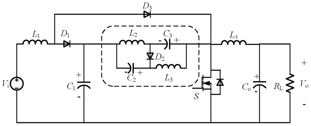
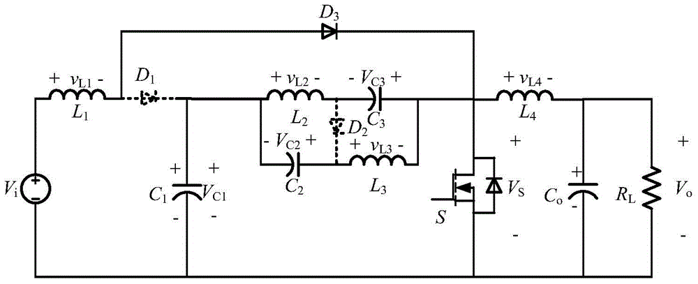
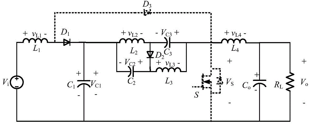
[0014] reference figure 1 , The current continuous high gain DC-DC converter circuit of the present invention includes a voltage source V i , The first inductance L 1 , The first diode D 1 , The first capacitor C 1 , By the second inductor L 2 , The third inductor L 3 , The second capacitor C 2 , The third capacitor C 3 And the second diode D 2 The impedance network formed at both ends (such as figure 1 Shown in the dashed box), the third diode D 3 , MOS tube S, fourth inductor L 4 , Output capacitance C o And load R L . The voltage source V i , The first inductor L 1 , The third diode D 3 And MOS tube in series to form a first-stage boost circuit; the first capacitor C 1 , The impedance network at both ends and the MOS tube S are connected in series to form a second-stage boost circuit; the fourth inductor L 4 , Output capacitor C o And load ...


PUM


Abstract

The invention provides a current continuous type high-gain DC-DC converter circuit. The current continuous type high-gain DC-DC converter circuit comprises a voltage source, a first inductor, a first diode, a first capacitor, a two-end impedance network, a third diode, an MOS transistor, a fourth inductor, an output capacitor and a load, wherein the two-end impedance network is composed of a second inductor, a third inductor, a second capacitor, a third capacitor and a second diode. The voltage source, the first inductor, the third diode and the MOS transistor are sequentially connected in series to form a first level booster circuit, the first capacitor, the two-end impedance network and the MOS transistor are sequentially connected in series to form a second level booster circuit, and the fourth inductor, the output capacitor and the load form an output circuit. The whole circuit is simple in structure, only one MOS transistor is adopted, high output voltage gains are possessed, power currents are continuous, load currents are continuous, input and output are both grounded, voltage stress of the capacitors in the two-end impedance network is low, and starting impulse currents and impulse currents generated at the moment the MOS transistor is switched on do not exist in the circuit.

Description

Technical field [0001] The invention relates to the technical field of power electronic circuits, in particular to a current continuous high-gain DC-DC converter circuit. Background technique [0002] In fuel cell power generation and photovoltaic power generation, due to the low DC voltage provided by a single solar cell or a single fuel cell, it cannot meet the electricity demand of existing electrical equipment, nor can it meet the demand for grid connection. It is often necessary to connect multiple batteries Connect in series to achieve the required voltage. On the one hand, this method greatly reduces the reliability of the entire system, on the other hand, it also needs to solve the problem of series voltage equalization. For this reason, a high-gain DC-DC converter capable of converting low voltage to high voltage is required. The Z-source boost DC-DC converter proposed in recent years is a high-gain DC-DC converter, but the circuit has a high impedance network capacito...

Claims


Application Information

Patent Timeline
Patent Type & Authority Applications(China)
IPC IPC(8): H02M3/155
Inventor 丘东元杨立强张波张桂东黄子田
Owner SOUTH CHINA UNIV OF TECH
Why Eureka
Try Eureka