Coupled inductor-type three-level Zeta converter

A technology of coupled inductors and converters, applied in the direction of adjusting electrical variables, converting DC power input to DC power output, instruments, etc., can solve problems such as voltage conversion ratio switching duty cycle dependence

Inactive Publication Date: 2015-10-07
HARBIN INST OF TECH
View PDF5 Cites 10 Cited by
  • Summary
  • Abstract
  • Description
  • Claims
  • Application Information

AI Technical Summary

Problems solved by technology

[0005] In order to solve the problem that the voltage gain of the circuit is greatly improved in the existing DC-DC converter using switched inductors and switched capacitor structural units, because the voltage gain is limited by the value of the duty cycle, the voltage conversion of the circuit Compared with the problem of over-reliance on the selection of the switch duty cycle, a coupled inductor type three-level Zeta converter is proposed

Method used


Image

  • Coupled inductor-type three-level Zeta converter
  • Coupled inductor-type three-level Zeta converter
  • Coupled inductor-type three-level Zeta converter

Examples


specific Embodiment approach 1

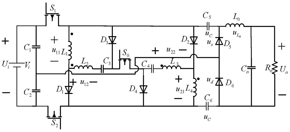
[0028] Specific implementation mode 1, refer to figure 1 Describe this implementation mode specifically, a kind of coupled inductance type three-level Zeta converter described in this implementation mode, it comprises: power supply V i , capacitance C 0 , capacitance C 1 , capacitance C 2 , capacitance C 3 , capacitance C 4 , capacitance C 5 , capacitance C 6 , switch tube S 0 , switch tube S 1, switch tube S 2 , Diode D 1 , Diode D 2 , Diode D 3 , Diode D 4 , Diode D 5 , Diode D 6 , resistance R 0 , inductance L 0 , coupled inductance L 1 , coupled inductance L 2 , coupled inductance L 3 and coupled inductor L 4 ; Coupled inductance L 1 and coupled inductor L 2 Mutual coupling; coupled inductance L 3 and coupled inductor L 4 Mutual coupling;

[0029] Power V i The anode of the switch tube S is connected at the same time 1 source and capacitor C 1 One end of the power supply V i The negative pole of the switch tube S is connected at the same time ...

specific Embodiment approach 2

[0060] Embodiment 2. This embodiment is a further description of a coupled inductance three-level Zeta converter described in Embodiment 1. In this embodiment, the coupled inductor L 1 and coupled inductor L 4 The number of turns of the coil is N 1 ; Coupled inductance L 2 and coupled inductor L 3 The number of turns of the coil is N 2 ; where N 1 and N 2 All are positive integers.

specific Embodiment approach 3

[0061]Specific Embodiment 3. This specific embodiment is a further description of a coupled inductance type three-level Zeta converter described in Specific Embodiment 1. In this embodiment, the power supply U i The voltage is 10V.


PUM


Abstract

The invention discloses a coupled inductor-type three-level Zeta converter, which relates to the technical field of power electronics converters and aims at solving the problem that as voltage gain is limited by the value of a duty ratio, a voltage conversion ratio of the circuit depends too much on selection of the switch duty cycle. Primary ends of the coupled inductors in the circuit are connected in parallel with a power supply when two main switch transistors are conducted, the power supply charges the coupled inductors, n times of voltage are generated at the secondary ends of the coupled inductors correspondingly, voltage at two ends of bootstrap capacitors is enhanced to n+1 times of power voltage. When one of the two main switch transistors is cut off, the primary ends and the secondary ends of the two coupled inductors are serially connected together in the circuit for discharging. According to a volt-second balance circuit effect principle, the circuit can realize high voltage gain. As the circuit introduces a turn ratio of the coupled inductor, dependence on the duty cycle value by the voltage gain is fully reduced. The coupled inductor-type three-level Zeta converter can be used for changing the topological structure of a DC converter main circuit.

Description

technical field [0001] The invention relates to the technical field of power electronic converters. Background technique [0002] High-gain DC-DC converters are widely used in green energy systems, but currently most DC-DC converters used in various fields are two-level converters. When the three-level DC-DC converter and the two-level circuit structure have the same voltage gain, the voltage stress at both ends of power switching devices such as switch tubes and diodes is only half of that of the two-level conversion circuit. At the same time, when the switching frequency of the driving signal is the same, and the ripple of the inductor current and the capacitor voltage are also the same, the value of the energy storage elements such as the inductor and capacitor is only half of that of the original two-level circuit. [0003] But because the voltage gain of the traditional three-level DC-DC converter is the same as that of the two-level circuit, it cannot achieve a higher...

Claims


Application Information

Patent Timeline
Patent Type & Authority Applications(China)
IPC IPC(8): H02M3/155
Inventor 刘洪臣管恩慧李飞
Owner HARBIN INST OF TECH
Why Eureka
Try Eureka