Burner fire cover and gas cooker using the fire cover

A burner and fire cover technology, applied in the direction of burners, gas fuel burners, applications, etc., can solve the problems of unfavorable stove combustion efficiency, high requirements for stove dampers, and high air velocity, so as to reduce the blockage of fire transmission grooves probability, better fire transmission performance, and enhanced applicability

Active Publication Date: 2022-01-25
NINGBO FOTILE KITCHEN WARE CO LTD
View PDF13 Cites 0 Cited by
  • Summary
  • Abstract
  • Description
  • Claims
  • Application Information

AI Technical Summary

Problems solved by technology

[0004] The open fire transmission tank has the following defects: First, the open fire transmission tank is easy to cause blockage of the fire transmission tank, that is, the soup flowing down from the bottom of the pot is easy to flow into the fire transmission tank, and the blockage will affect the fire transmission performance. The main reason for the blockage and maintenance of the fire transmission channel; second, the open fire transmission channel has high requirements on the damper of the cooker, because after the damper is opened, too much air at one time will cause the air velocity to be too high, which will cause the flame to leave the flame or fall out during combustion. Therefore, the structural feature of the open fire transfer trough is poor flame stability. Therefore, to ensure the fire transfer performance of the open fire transfer trough, it is basically to close the damper very small, but the small damper is not conducive to the operation of the stove. The combustion efficiency is also not conducive to the emission of smoke, which greatly affects the performance of the stove
[0006] The fire transmission structure prevents the fire groove from being blocked by the fire transmission cover, but the setting of the fire transmission cover will also have an adverse effect on the entry of secondary air, and there is no flame stabilization structure in the fire transmission channel, and the flame stabilization effect is not good

Method used


Image

  • Burner fire cover and gas cooker using the fire cover
  • Burner fire cover and gas cooker using the fire cover
  • Burner fire cover and gas cooker using the fire cover

Examples


Embodiment 1

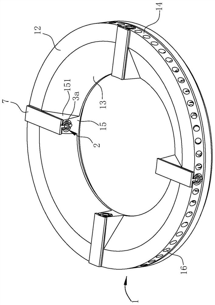
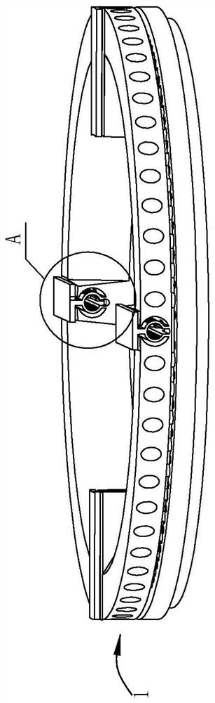
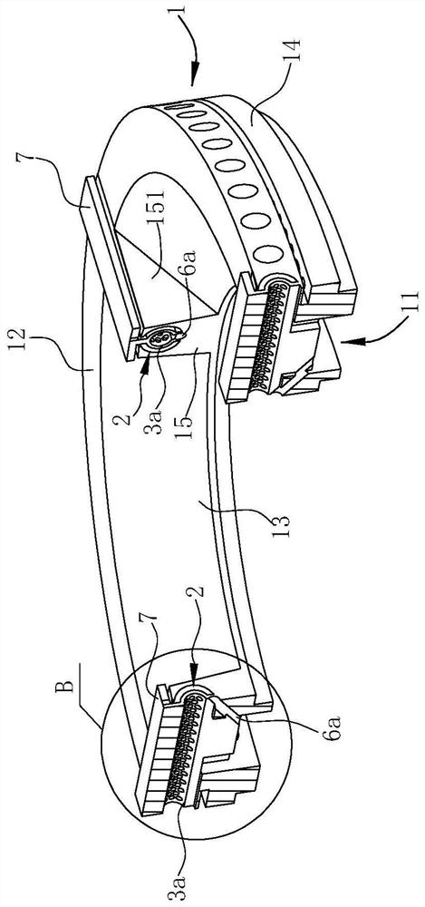
[0040] like Figure 1 ~ 7 As shown, the combustor fire cover of the preferred embodiment includes a circular cover body 1, which is provided in a fire groove 2 at the top of the fire cover body 1, and the separator 3a, which is provided in the fire groove 2, and The cover plate 7 above the fire. In this embodiment, four of the fire grooves 2 have four in the center of the fire cover body 1 in the top of the fire cover body 1, and the length direction of the fire cover 2 along the radial direction of the fire cover body 1, each The flow of fire grooves 2 corresponds to a cover plate 7, a partition member 3a, which is described hereinafter in which one of the flux 2 is described. In this paper, "within" refers to the center of the fire cover body 1, "outside" refers to the center of the fire cover body 1.

[0041] like Figure 1 ~ 4 As shown, the fire cover body 1 includes an annular top wall 12 and an inner ring wall 13 and an outer ring wall 14 that extend vertically or inclined dow...

Embodiment 2

[0052] like Figure 8 ~ 14 As shown, the difference from Embodiment 2 and Example 1 is that the partition member 3b and the convex groove 2 are different, and the separator 3b of the present embodiment is in a plate shape, and the longitudinal section of the wireless groove 2 is in type C.

[0053] In the present embodiment, the separator 3b is vertically disposed, and the upper end extends the transfer fluid groove 2 is connected to the cover plate 7, and such a transmitting groove 2 is separated from the partition 3b in two regions in the width direction, The two regions are located on both sides of the separator 3b, and the through hole 31b penetrates the wall thickness of the separator 3b. Thus, both sides of the spacer 3b are integrated and independently, the small holes (ie, through holes 31b) have a steady effect, the effect is best, so that the fire is more smooth and the wind does not affect the wind, and can be bilateral Supplement of secondary air, double-sided fire, mor...

Embodiment 3

[0056] Example 3 is a gas stove having a fire cover of Example 2:

[0057] like Figure 15 , 16 As shown, the cooker further includes a base 0 and an inner ring flam cover 8, and the fire cover body 1 is enabled outside the inner ring cover 8 and forms an annular passage 81 between the two, and an ignition needle 9 is provided in the annular passage 81. There are two discharge electrodes 91 of the ignition needle 9, and the two discharge electrodes 91 points to the inner ring flakes 82 and the inner ring fire hole 8 of the inner loop fire cover 8, even if one of the discharge electrodes 91 is poor, the other is also Can work for ignition.

[0058] The fire cover body 1, the inner ring fire 8, and the ignition needle 9 are all set on the base 0, which is prior art, and details are not described herein again.


PUM


Abstract

The invention relates to a burner fire cover and a burner cooker using the fire cover, wherein the fire cover includes a ring-shaped fire cover body, the bottom of the fire cover body has an air mixing chamber, and the top of the fire cover body is provided with a The fire transmission groove penetrates along its radial direction, and the fire transmission groove is in fluid communication with the gas mixing chamber. The groove is divided into two regions, the length direction of the fire transfer groove is along the radial direction of the fire cover body, the partition is provided with through holes, and the two regions in the fire transfer groove pass through the The through holes are in fluid communication. The present invention divides the fire transfer tank into two areas by setting a partition, and the two areas are connected through a through hole, so that the two areas are integrated and independent of each other, and can stabilize the flame with each other, so that the transmission The fire is stable and reliable.

Description

Technical field [0001] The present invention belongs to the field of gas cookers, and more particularly to a combustor fire cover and a gas cooker to which the fire is applied. Background technique [0002] At present, the turning fire structure of the burner on the market is mainly from the flame of the inner ring. The fire hole of the outer ring is transmitted through the wireway to ignite the outer ring fire; during transmission, due to the independent structure of the inner and outer ring, it is necessary to set up The fire is turned on. [0003] The outer ring fire cover of the existing gas burner generally uses an open firing structure, such as the Chinese invention patent "a gas cooker burner fire cover", a patent number, which is 201610930412.4 (public numeral CN106642118A). For the 200920202204.8 (authorized bulletin No. CN201555225U) China Utility New Type Patent, the patent number 201420411586.6 (authorized bulletin is CN204006006U), China's utility model patent "," a ...

Claims


Application Information

Patent Timeline
Patent Type & Authority Patents(China)
IPC IPC(8): F23D14/46F23D14/58F23D14/62F23D14/84F23D14/26F24C3/08F24C3/10
CPCF23D14/46F23D14/62F23D14/58F23D14/26F23D14/84F24C3/085F24C3/103
Inventor 吴丽波
Owner NINGBO FOTILE KITCHEN WARE CO LTD
Why Eureka
Try Eureka