Mold half and method for producing injection molded part having at least one insert

A technology of embedded parts and injection molded parts, applied in the direction of coating, etc., can solve the problems of cumbersome cost, cumbersome manipulation and positioning, and high cost, and achieve the effect of saving space

Active Publication Date: 2021-04-09
LISA DRAXLMAIER GMBH
View PDF7 Cites 0 Cited by
  • Summary
  • Abstract
  • Description
  • Claims
  • Application Information

AI Technical Summary

Problems solved by technology

[0003] The manipulation and positioning of such inserts in the cavity area of ​​an injection mold can sometimes be quite tedious
This can come with cumbersome and costly peripheral parts, long cycle times and considerable space requirements for injection molding machines

Method used


Image

  • Mold half and method for producing injection molded part having at least one insert
  • Mold half and method for producing injection molded part having at least one insert
  • Mold half and method for producing injection molded part having at least one insert

Examples


Embodiment Construction

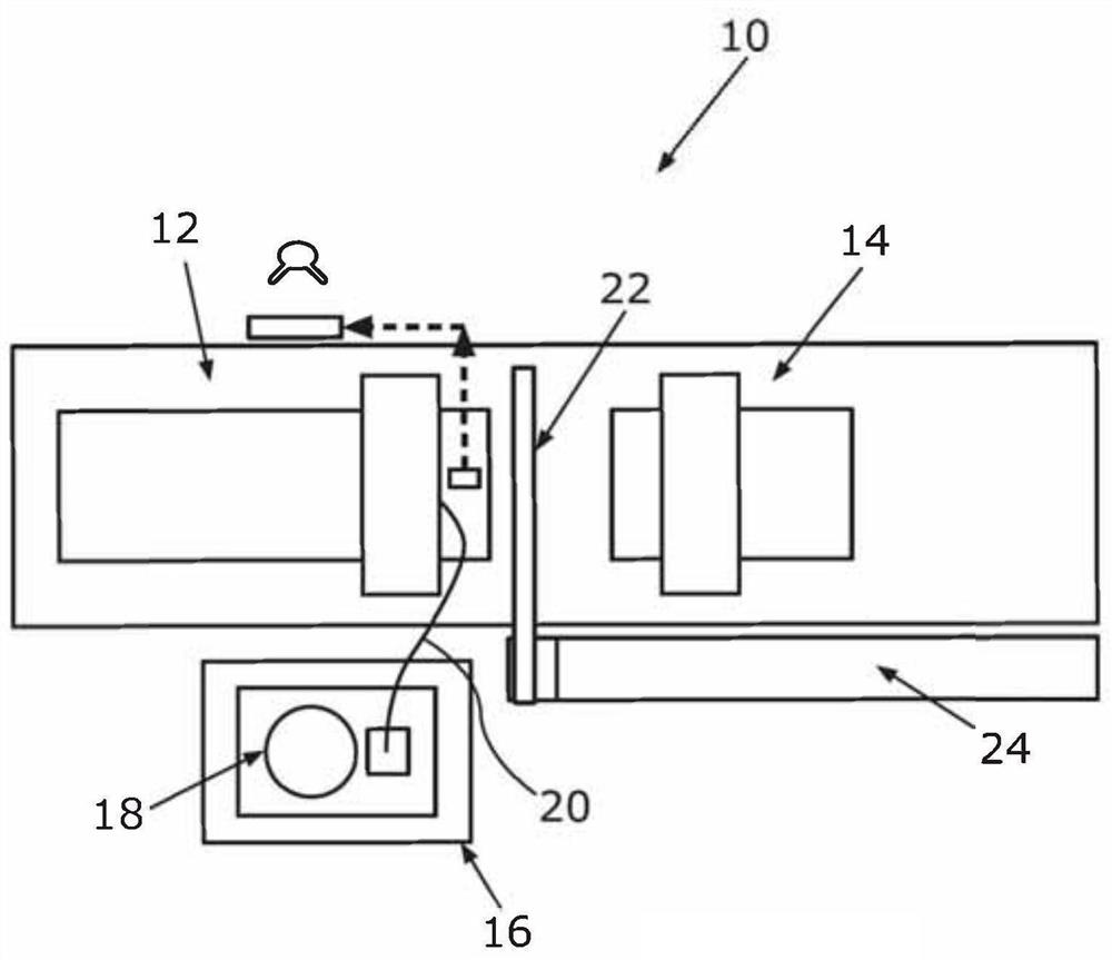
[0038] exist figure 1 The injection molding machine 10 is shown in a schematic top view of . The injection molding machine 10 comprises two mold halves 12 , 14 with which injection molded parts can be produced with injection-molded inserts. The mold half 12 on the left according to the illustration includes an integrated feed mechanism, by means of which inserts can be fed into the area of ​​the cavity of the two mold halves 12 , 14 . The injection molding machine 10 may also include a supply enclosure 16 which may have a shake tank 18 for stocking and separating keyed inserts. The supply periphery 16 can also have a hose 20 by means of which the separate inserts can be supplied to the mold halves 12 pneumatically, for example. The entire supply periphery 16 can be designed to be removable, ie it can be supplied to different injection molding machines 10 as required. The injection molding machine 10 can also have a linear manipulator 22 or a robot, by means of which the pro...


PUM


Abstract

The invention relates to a mold half (12) for an injection molding machine (10) for producing an injection molded part with at least one insert (32). The invention also relates to a method for producing an injection molded part having at least one insert (32).

Description

technical field [0001] The invention relates to a mold half and a method for producing an injection molded part with at least one insert. Background technique [0002] It is already known to integrate inserts into injection molded parts. For this purpose, such an insert is arranged in the region of the cavity of the injection mold and is at least partially injection-molded with plastic. Such inserts can serve, for example, as mechanical interfaces at which further components can be connected to the associated injection molded part. Inserts, for example in the form of screws, pins, pins, mating pins, sleeves, collar sleeves, threaded sleeves, nuts, etc., can thus be integrated into these injection-molded parts during their manufacture. [0003] The manipulation and positioning of such inserts in the cavity region of the injection mold can sometimes be quite cumbersome. This can be accompanied by cumbersome and cost-intensive peripheral parts, long cycle times and considera...

Claims


Application Information

Patent Timeline
Patent Type & Authority Applications(China)
IPC IPC(8): B29C45/14B29C45/26
CPCB29C45/14065B29C45/14008B29C45/14336B29C45/2602B29C45/14032B29C45/14073B29C2045/14139B29C45/762B29C2045/1409
Inventor 彼得·埃斯特勃斯蒂梵·波斯谢尔赫尔曼·皮特莱策丹尼尔·格蕾芬得雷纳·利特克
Owner LISA DRAXLMAIER GMBH
Why Eureka
Try Eureka