Automatic machine gun positioning sliding seat for military helicopter

An automatic positioning and helicopter technology, which is applied to seat arrangement, military equipment configuration, aircraft parts, etc., can solve the problems of small rotation angle of rotating gun frame, affecting shooting accuracy, and failing to meet shooting requirements, etc.

Active Publication Date: 2021-04-20
北京天创凯睿科技有限公司
View PDF17 Cites 3 Cited by
  • Summary
  • Abstract
  • Description
  • Claims
  • Application Information

AI Technical Summary

Problems solved by technology

[0003] The purpose of the present invention is to provide a machine gun automatic positioning sliding seat for military helicopters, to solve the problem that the rotation angle of the rotating gun rack in the prior art is small and cannot meet the shooting requirements of a large angle, and the operator needs to realize the angle by himself. Rotation, problems affecting shooting accuracy

Method used


Image

  • Automatic machine gun positioning sliding seat for military helicopter
  • Automatic machine gun positioning sliding seat for military helicopter
  • Automatic machine gun positioning sliding seat for military helicopter

Examples


Embodiment 1

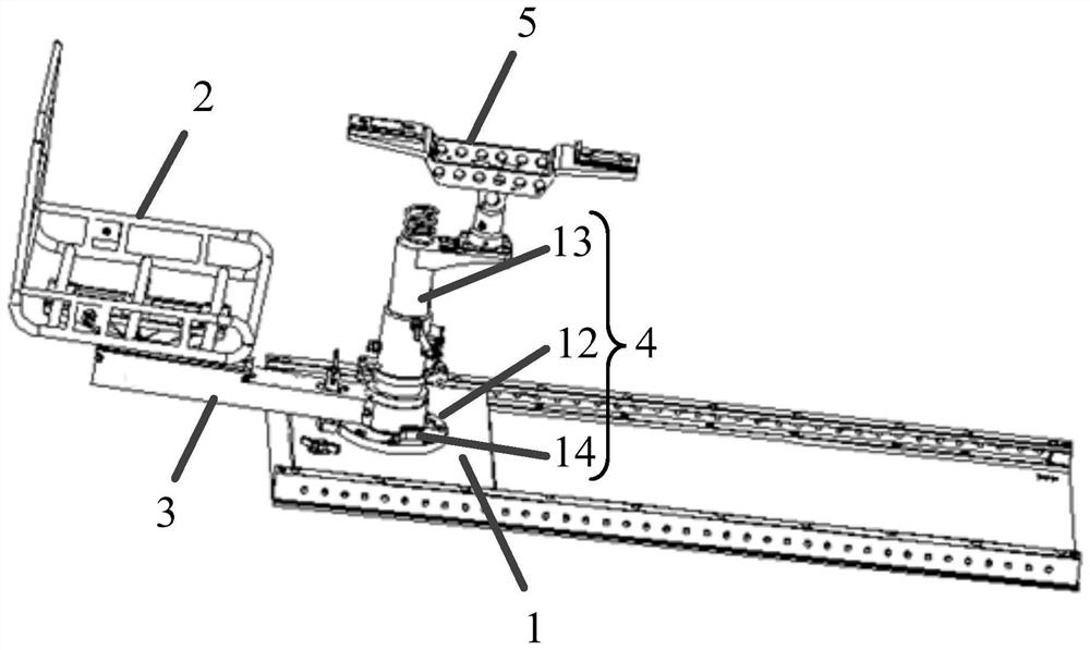
[0083] A machine gun self-positioning sliding seat for military helicopters is documented as figure 1 shown, which includes:

[0084] seat base 1;

[0085] Sliding seat 2, the sliding seat 2 is provided with a sliding guide rod 3; one end of the sliding guide rod 3 is fixedly connected with the sliding seat 2, and the other end is connected with the positioning seat 4 through a hinge structure to guide The sliding seat 2 is driven and slidably arranged on the seat base 1 along the arc-shaped guide track;

[0086] The machine gun frame 5 is rotatably arranged on the positioning seat 4 for fixing the machine gun;

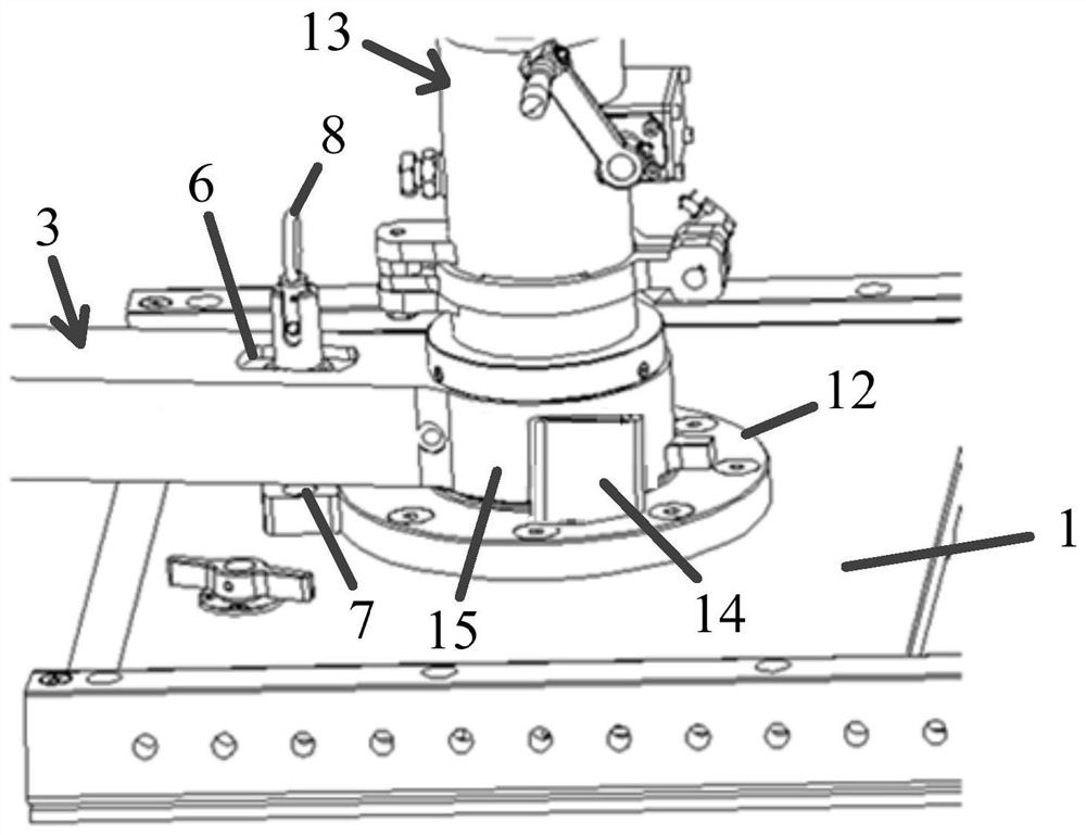
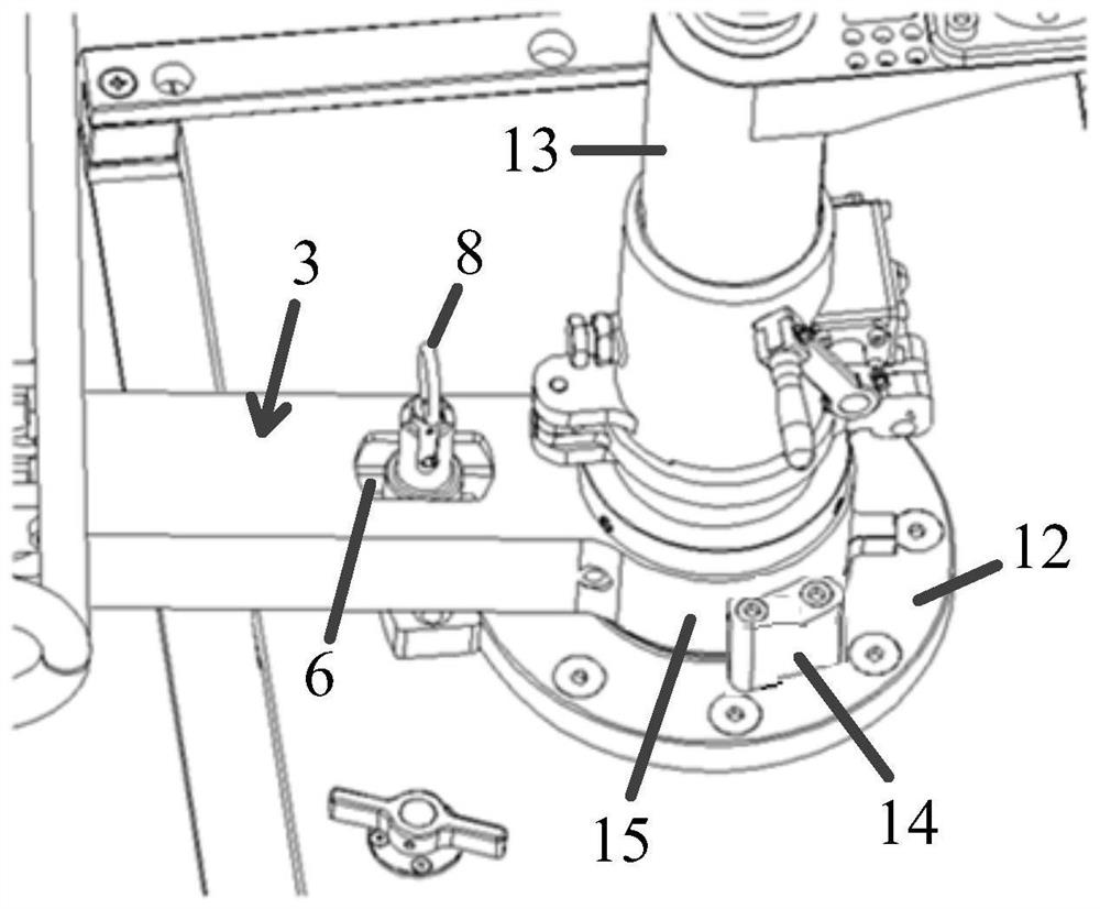
[0087] The positioning mechanism includes: a first positioning hole 6 provided on the sliding guide rod 3, a second positioning hole 7 provided on the seat base 1 and adapted to the first positioning hole 6, and The positioning pin 8 that is slidably arranged in the first positioning hole 6 and is mated with the second positioning hole 7; side and is located at th...

Embodiment 2

[0099] A machine gun self-positioning sliding seat for military helicopters is described, comprising:

[0100] seat base 1;

[0101] Sliding seat 2, the sliding seat 2 is provided with a sliding guide rod 3; one end of the sliding guide rod 3 is fixedly connected with the sliding seat 2, and the other end is connected with the positioning seat 4 through a hinge structure to guide The sliding seat 2 is driven and slidably arranged on the seat base 1 along the arc-shaped guide track;

[0102] The machine gun frame 5 is rotatably arranged on the positioning seat 4 for fixing the machine gun;

[0103] The positioning mechanism includes: a first positioning hole 6 provided on the sliding guide rod 3, a second positioning hole 7 provided on the seat base 1 and adapted to the first positioning hole 6, and The positioning pin 8 that is slidably arranged in the first positioning hole 6 and is mated with the second positioning hole 7; side and is located at the central position in th...

Embodiment 3

[0106] The difference between this embodiment and embodiment 1 is that, as Figure 4 As shown, the positioning seat 4 includes: a fixed base plate 12, a rotating column 13 fixedly arranged on the fixed base plate 12; The rotating column 13 is sleeved and connected in rotation; the pop-up airbag 9 is embedded in the side of the collar 15 close to the sliding guide rod 3 . The pop-up airbag 9 is an annular cylindrical airbag matching the shape of the sliding guide rod 3 .

[0107] In this embodiment, the collar 15 is provided with an accommodating groove for accommodating the pop-up airbag 9, and the pop-up airbag 9 is bonded to the wall of the accommodating groove; When the pop-up airbag 9 is inflated, the pop-up airbag 9 overcomes the adhesive force and moves out of the accommodating groove.


PUM


Abstract

An automatic machine gun positioning sliding seat for a military helicopter comprises a seat base; a sliding seat which is provided with a sliding guide rod; a machine gun rack which is rotationally arranged on the positioning seat; a positioning mechanism which comprises a first positioning hole formed in the sliding guide rod, a second positioning hole formed in the seat base and matched with the first positioning hole, and a positioning pin arranged in the first positioning hole in a sliding mode and connected with the second positioning hole in a matched and inserted mode. The first positioning hole is formed in the side, close to the positioning base, of the sliding guide rod and located in the center of the width direction of the sliding guide rod. The sliding seat also comprises a collision protection mechanism. By means of the structure, the problems that in the prior art, a rotating gun frame is small in rotating angle, the large-angle shooting requirement cannot be met, an operator needs to achieve angle rotation by himself / herself, and the shooting accuracy is affected are solved.

Description

technical field [0001] The invention relates to the technical field of aircraft machine gun supporting mechanisms, in particular to a machine gun automatic positioning sliding seat used for military helicopters. Background technique [0002] Military helicopters need to be provided with machine guns at the position of the door during flight, and fighters sit on the machine gun seats in the cabin and attack targets outside the cabin by rotating the position. The machine gun auxiliary equipment of the existing military helicopters usually realizes attacking targets at different angles outside the cabin of the military helicopter by arranging a rotating gun mount for fixing the machine gun. However, the above-mentioned rotating gun rack has the following problems: 1. The rotation angle is relatively small, so it cannot meet the shooting requirements at a larger angle under the condition that the position of the aircraft remains unchanged. 2. When shooting the target through th...

Claims


Application Information

Patent Timeline
IPC IPC(8): B64D11/06B64D7/06
Inventor 刘桂成崔明宝王文良
Owner 北京天创凯睿科技有限公司
Why Eureka
Try Eureka