Stamping device for machining storage battery shell and stamping method thereof

A stamping device and battery shell technology, which is applied in the direction of feeding device, positioning device, stripping device, etc., can solve the problems of raw material plate warping, inconvenient operation, low stamping efficiency, etc., achieve smooth punching, prevent warping, and improve The effect of utilization

Pending Publication Date: 2021-04-27
安徽强旭塑业科技有限公司
View PDF7 Cites 1 Cited by
  • Summary
  • Abstract
  • Description
  • Claims
  • Application Information

AI Technical Summary

Problems solved by technology

[0005] The purpose of the present invention is to solve the problem that in the prior art, the stamping device for battery shell processing is unstable for the placement of the raw material plate, and the edge warping of the raw material plate is prone to occur, resulting in waste of raw materials. The traditional stamping device needs to manually carry the raw material. , so that the stamping efficiency is low. Among them, some feeding devices can only stamp a certain fixed size raw material plate, so as to manufacture a battery case with a fixed size pair; in addition, the stamping table is relatively high, and the operation is difficult. The work intensity of the staff is improved, the operation is inconvenient, and it is inconvenient to collect the stamped raw material plates. A stamping device and stamping method for battery shell processing are proposed

Method used


Image

  • Stamping device for machining storage battery shell and stamping method thereof
  • Stamping device for machining storage battery shell and stamping method thereof
  • Stamping device for machining storage battery shell and stamping method thereof

Examples


Embodiment Construction

[0034] The technical solutions of the present invention will be clearly and completely described below in conjunction with the embodiments. Apparently, the described embodiments are only some of the embodiments of the present invention, not all of them. Based on the embodiments of the present invention, all other embodiments obtained by persons of ordinary skill in the art without creative efforts fall within the protection scope of the present invention.

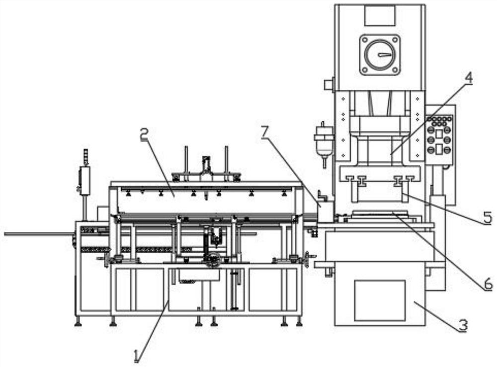
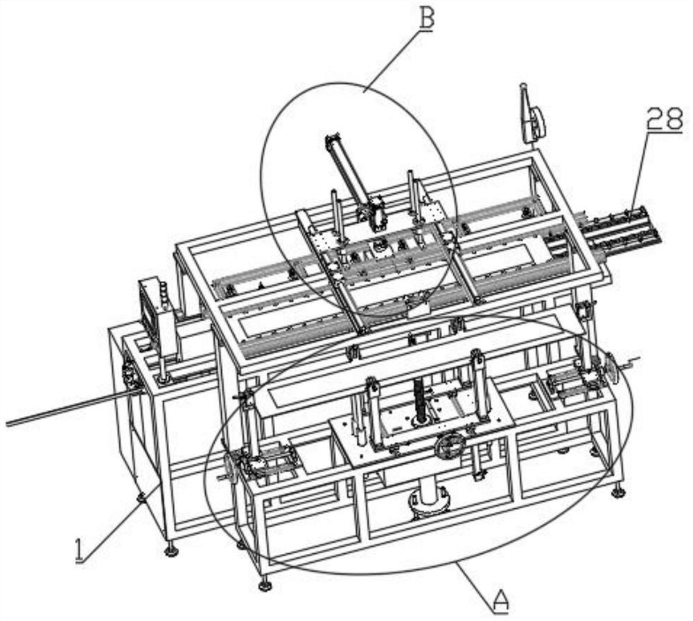
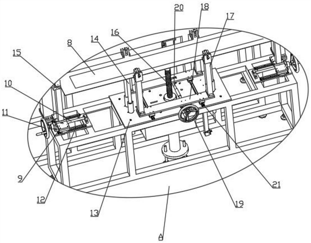
[0035] see Figure 1-6 As shown, a punching device for battery case processing includes a bracket 1, a feeding mechanism 2, a processing table 3, a punching machine 4, an upper mold 5, a lower mold 6, and a positioning mechanism 7;

[0036] The top surface of the processing table 3 is provided with a lower die 6, and the top of the processing table 3 is provided with a punching machine 4, and the output end of the punching machine 4 is connected with the upper die 5, and the upper die 5 is located directly above the lower d...


PUM


Abstract

The invention discloses a stamping device for machining a storage battery shell. The stamping device comprises a support, a feeding mechanism, a machining table, a stamping machine, an upper die, a lower die and a positioning mechanism, a positioning mechanism is arranged at one end, close to the stamping machine, of a conveyor belt, a fixing frame is of a U-shaped structure and is mounted on the conveyor belt, the bottom end of a third screw rod penetrates through the top surface of the fixing frame and is in threaded connection with the fixing frame, the bottom end of the third screw rod is rotatably connected with a limiting plate, the limiting plate is in sliding connection with an inner wall of the fixing frame, the top end of the third screw rod is connected with a handle, the feeding mechanism comprises a jacking mechanism, a material taking mechanism and the conveyor belt, the conveyor belt is horizontally arranged on the support, the conveyor belt and the lower die of the machining table are located on the same plane, the material taking mechanism is arranged above the conveyor belt, and the jacking mechanism is arranged in front of the conveyor belt. According to the stamping device, automatic stamping is achieved when the storage battery shell is machined, material plates of different sizes can be stamped according to the production requirement, and the storage battery shells of different sizes are manufactured.

Description

technical field [0001] The invention belongs to the technical field of battery case processing, and relates to a stamping device and a stamping method thereof, in particular to a stamping device and a stamping method for processing a battery case. Background technique [0002] The shell of the storage battery is used to hold the electrolyte and the plate assembly. The shell should be acid-resistant, heat-resistant, and shock-resistant. It was mostly made of hard rubber in the past. [0003] The comparative document CN210450503U discloses a stamping device for auto parts processing, which relates to the technical field of stamping devices, specifically a stamping device for auto parts processing, including a stamping device body, and an upper pressing plate is fixedly installed on the top of the stamping device body. A stamping table is arranged inside the stamping device body, and a worm wheel support leg is clamped on the bottom of the stamping device body. The stamping de...

Claims


Application Information

Patent Timeline
Patent Type & Authority Applications(China)
IPC IPC(8): B21D43/12B21D43/13B21D43/18B21D45/08B21D28/02B21D43/22
CPCB21D43/12B21D43/13B21D43/18B21D45/08B21D28/02B21D43/22B21D43/026
Inventor 王振伟朱保红
Owner 安徽强旭塑业科技有限公司
Why Eureka
Try Eureka