

Round material straightening device and straightening method thereof
A round material and straightening technology, which is applied in the field of round material straightening devices to achieve the effect of eliminating tail blind area and local small bending
- Summary
- Abstract
- Description
- Claims
- Application Information
AI Technical Summary
Problems solved by technology
Method used
Image

Examples
Embodiment 1
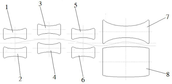
[0029] refer to figure 1 and figure 2 , The present invention proposes a round bar straightening device, including a frame, the frame is a frame structure, the frame is directly or indirectly assembled with: a first upper drive roller 1 and a first lower drive roller 1 and a first lower drive that are arranged up and down correspondingly. Roller 2; the second upper transmission roller 3 and the second lower transmission roller 4 arranged up and down correspondingly; the third upper transmission roller 5 and the third lower transmission roller 6 arranged up and down correspondingly; the upper concave roller 7 and the lower convex roller arranged up and down correspondingly Roller 8; wherein, the first upper transmission roller 1, the first lower transmission roller 2, the second upper transmission roller 3, the second lower transmission roller 4, the third upper transmission roller 5 and The third lower transmission rollers 6 are distributed along the straightening direction ...
Embodiment 2
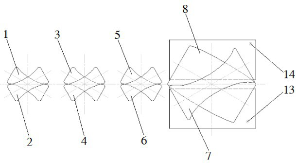
[0033] refer to figure 1 , figure 2 , image 3 and Figure 4 , on the basis of Embodiment 1, it also includes a plurality of upper roller frames 9 and a plurality of lower roller frames 11, the first upper transmission roller 1, the second upper transmission roller 3, the third upper transmission roller 5 and the upper concave roller 7 are rotatably arranged on the corresponding upper roller frame 9, the first lower transmission roller 2, the third lower transmission roller 6 and the lower convex roller 8 all rotate are arranged on the respective lower roller frames 11 corresponding to each other.
[0034] A plurality of upper roller frames 9 and a plurality of lower roller frames 11 are divided into upper and lower rows and are vertically assembled on the frame and aligned in the horizontal direction. The first upper drive roller 1, the second upper drive roller 3, the third upper roller Both ends of the movable roller 5 and the upper concave roller 7 are laterally assem...
Embodiment 3
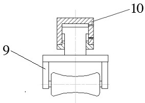
[0036] refer to image 3 , On the basis of Embodiment 2, one end of each of the upper roller frames 9 is provided with an upper roller piston cylinder 10 .
[0037] The upper roller piston cylinder 10 is fixed on the frame, the height of each upper roller frame 10 on the frame can be adjusted separately through the upper roller piston cylinder 10, and the first upper drive roller 1 and the second lower drive roller can be adjusted according to the diameter of the round material. Roll gap between rolls 2, roll gap between second upper drive roll 3 and second lower drive roll 4, roll gap between third upper drive roll 5 and third lower drive roll 6, and upper concave roll 7 Roll gap with lower convex roll 8.
PUM
 Abstract
Description
Claims
Application Information