


Quick Research
Generate reliable direction feasibility study reports for your R&D in just a few steps.

Technical Q&A
Discover and master advanced knowledge NOW. Basics, ideas, possibilities, all at once.

Find Solutions
As an expert in R&D theories, this can generate solutions to your technical problems instantly.

Evaluate Feasibility
Analyze your overall solution with one click, know your potential R&D risks in advance.

Monitor Landscape
Get weekly tech updates, stay abreast of the latest tech innovations and key insights.
Combined round material straightening device and straightening method thereof
A combined and round bar technology is applied in the field of combined round bar straightening devices to achieve the effect of eliminating local small bends
- Summary
- Abstract
- Description
- Claims
- Application Information
AI Technical Summary
Problems solved by technology
Method used
Image

Examples
Embodiment 1
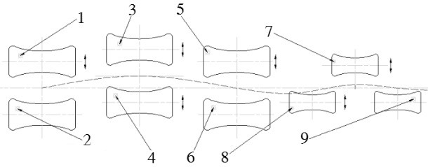
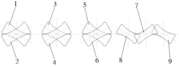
[0029] refer to figure 1 with figure 2 , the present invention proposes a combined round material straightening device, including a frame, the frame is a frame structure, and the frame is directly or indirectly equipped with: the first upper drive roller 1 and the first The lower transmission roller 2; the second upper transmission roller 3 and the second lower transmission roller 4 correspondingly arranged up and down; the third upper transmission roller 5 and the third lower transmission roller 6 correspondingly arranged up and down; the upper interlaced rollers 7, The first lower staggering roller 8 and the second lower staggering roller 9, the upper staggering roller 7 is located between the first lower staggering roller 8 and the second lower staggering roller 9 in the horizontal direction; wherein, the first lower staggering roller 9 One upper transmission roller 1, the first lower transmission roller 2, the second upper transmission roller 3, the second lower transmis...
Embodiment 2
[0032] refer to figure 1 , figure 2 , image 3 with Figure 4 , on the basis of embodiment 1, it also includes a plurality of upper roller stands 10 and a plurality of lower roller stands 11, the first upper transmission roller 1, the second upper transmission roller 3, the third upper transmission roller 5 and the upper interlaced rollers 7 are horizontally rotated and arranged on the corresponding upper roller frames 10, the first lower transmission roller 2, the third lower transmission roller 6, the first lower interlaced roller 8 and the second lower interlaced rollers 9 are both horizontally rotatably arranged on the corresponding lower roller frames 11 .
[0033] refer to figure 1 , a plurality of upper roller frames 10 and a plurality of lower roller frames 11 are divided into upper and lower rows and assembled on the frame, refer to figure 2 , and aligned vertically, refer to image 3 The two ends of the first upper transmission roller 1, the second upper tran...
Embodiment 3
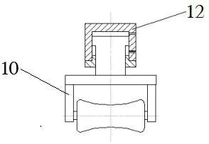
[0035] refer to image 3 , On the basis of Embodiment 2, one end of each of the upper roll stands 10 is provided with an upper roll piston cylinder 12 .
[0036] The upper roller piston cylinder 12 is fixed on the frame, and the height of each upper roller frame 10 on the frame can be adjusted through the upper roller piston cylinder 12, and the first upper driving roller 1 and the lower driving roller can be adjusted according to the diameter of the round material. The roll gap between the rollers 2, the roll gap between the second upper drive roll 3 and the second lower drive roll 4, and the roll gap between the third upper drive roll 5 and the third lower drive roll 6; can also be adjusted The roll gap between the interlacing roll 7 and the first lower interlacing roll 8 and the second lower interlacing roll 9 in the vertical direction.
PUM
 Abstract
Description
Claims
Application Information
 - R&D Engineer
- R&D Manager
- IP Professional
- Industry Leading Data Capabilities
- Powerful AI technology
- Patent DNA Extraction
Browse by: Latest US Patents, China's latest patents, Technical Efficacy Thesaurus, Application Domain, Technology Topic, Popular Technical Reports.
© 2024 PatSnap. All rights reserved.Legal|Privacy policy|Modern Slavery Act Transparency Statement|Sitemap|About US| Contact US: help@patsnap.com