Optical fiber beam combining and splitting device

A fiber combiner and fiber combiner technology, applied in the field of lasers, can solve the problems of violating the development trend of fiber lasers, increasing the complexity of fiber laser wiring and integration, and the number of devices, so as to improve the combination efficiency, simplify the layout, Effect of suppressing temperature rise rate

Active Publication Date: 2021-05-14
LASER FUSION RES CENT CHINA ACAD OF ENG PHYSICS
View PDF26 Cites 2 Cited by
  • Summary
  • Abstract
  • Description
  • Claims
  • Application Information

AI Technical Summary

Problems solved by technology

[0004] The inventor has repeatedly studied the existing pump beam combiner-buncher cascade structure, and found that there are two problems: one is that the number of devices used is large, and a total of A beam combiner / cluster not only increases the complexity of fiber laser layout, wiring and integration, but also goes against the development trend of fiber laser miniaturization and light weight.

Method used


Image

  • Optical fiber beam combining and splitting device
  • Optical fiber beam combining and splitting device
  • Optical fiber beam combining and splitting device

Examples


Embodiment 1

[0028] like Figure 4 As shown, a fiber combiner and splitter, using In terms of application effect, the laser beams in P input fibers 1 are synthesized and then distributed to M output fibers 2, which is equivalent to integrating multiple fiber combiners to reduce the number of optical components .

[0029] Specifically, the optical fiber combiner and splitter are regarded as integrating M type structure fiber combiner, with root input fiber 1, M output fiber 2, by using In the cross-section of the optical fiber bundle composed of two input optical fibers, the outer ring can accommodate more optical fibers than the inner ring. Compared with the original The fiber optic combiner can greatly reduce the equivalent tapering ratio of the optical fiber, improve the combining efficiency, and reduce the loss of optical devices. Among them, , the fiber combiner has P 1 One input fiber and one output fiber.

[0030] In addition, the fiber combiner and splitter have the fun...

Embodiment 2

[0034] like Figure 5 As shown, the same parts of this embodiment and Embodiment 1 will not be repeated, and the difference is:

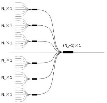
[0035] The number of optical fiber combiners and splitters is set to 2, and the post-stage cascaded fiber bundler of the fiber optic combiner and splitter adopts type structure, the number of input pump fibers of the fiber bundler . Since the optical fiber combiner and splitter integrates M Type structure fiber combiner, with root input fiber, M root output fiber, that is to say, the number of the output fiber and The number of type structured fiber combiners is equal. At the same time, P 1 There is no specific requirement, it can be an integer or a non-integer number, that is, the ratio of the number of input fibers to output fibers of the optical fiber combiner and splitter is not necessarily an integer.

Embodiment 3

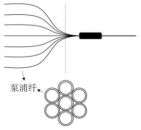
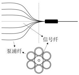
[0037] In the current scientific research and industrial lasers commonly used Pump combiner cascade The structure of the pump signal bundler is taken as an example (such as image 3 shown), treat the fiber combiner as a combination of 3 Fiber beam combiner (equivalent to pump beam combiner) forms fiber optic combiners and splitters (such as Figure 4 shown), then image 3 The shown structure transforms into Figure 5 As shown in the structure, the total number of optical components is reduced by 4. at the same time, Figure 4 Compared to figure 1 and figure 2 , only one more turn of the input fiber is arranged on the cross-section of the input fiber 1, that is, the cross-sectional area of ​​the input fiber 1 is slightly larger than the prior art, but, Figure 4 However, the total number of optical devices is significantly reduced, and at the same time, the synthesis loss and photothermal energy can be effectively reduced.

[0038] set up The beam combiner and ...


PUM

PropertyMeasurementUnit
diameteraaaaaaaaaa

Abstract

The invention relates to an optical fiber beam combining and splitting device, and belongs to the technical field of lasers, the optical fiber beam combining and splitting device adopts a type structure, and the application effect of the optical fiber beam combining and splitting device is that lasers in root input optical fibers are combined and then distributed into root output optical fibers, which is equivalent to the use of an individual type structure optical fiber beam combiner, wherein MxP1=P is the number of the input optical fibers and M>=2 is the number of the output optical fibers. The optical structure is an integrated structure, the characteristic that the outer ring can accommodate more optical fibers than the inner ring on the cross section of the optical fiber bundle formed by the root input optical fibers is fully utilized, and the equivalent tapering ratio of the optical fibers is reduced compared with that of a structural optical fiber beam combiner. According to the invention, the number of optical devices in the laser can be reduced, layout, wiring and integration of the laser are simplified, miniaturization and light weight of the laser are facilitated, and by adopting the type structure, the tapering ratio of the optical fiber can be reduced, the synthesis efficiency can be effectively improved, the thermal load can be reduced, and the temperature rise rate can be inhibited.

Description

technical field [0001] The invention belongs to the technical field of lasers, in particular to an optical fiber combiner and splitter. Background technique [0002] Fiber lasers generally use laser diodes as pump sources. In order to increase the laser power, a pump beam combiner is generally used to synthesize the pump light emitted by multiple laser diodes and inject it into the gain fiber of the fiber laser. For all-fiber lasers, this type of pump combiner is the fiber pump combiner (US 2018 / 0102623 A1), which Type structure - N pump fiber input, 1 fiber output, can directly superimpose the pump light from at most N pump sources into the same fiber, such as figure 1 shown. Optical fiber combiner is an optical fiber device prepared on the basis of fused tapered optical fiber bundles. A bundle of optical fibers is stripped of the coating, then arranged together in a certain way, heated at high temperature to melt, and the optical fiber bundle is stretched at the same t...

Claims


Application Information

Patent Timeline
Patent Type & Authority Applications(China)
IPC IPC(8): G02B6/28H01S3/094
CPCG02B6/28G02B6/2804H01S3/094042H01S3/094053
Inventor 刘玙吴文杰宋华青黄珊陶汝茂沈本剑李敏冯曦
Owner LASER FUSION RES CENT CHINA ACAD OF ENG PHYSICS
Why Eureka
Try Eureka