Depth imaging method and system for TIRF illumination

An imaging method and imaging system technology, applied in the direction of material excitation analysis, fluorescence/phosphorescence, instruments, etc., can solve problems such as inability to complete deep imaging

Pending Publication Date: 2021-05-18
广东粤港澳大湾区黄埔材料研究院
View PDF5 Cites 0 Cited by
  • Summary
  • Abstract
  • Description
  • Claims
  • Application Information

AI Technical Summary

Problems solved by technology

But because the evanescent wave is only a thin layer and can only propagate in the optically spars...

Method used


Image

  • Depth imaging method and system for TIRF illumination
  • Depth imaging method and system for TIRF illumination
  • Depth imaging method and system for TIRF illumination

Examples


Embodiment Construction

[0039] The present invention will be further described below in conjunction with drawings and embodiments.

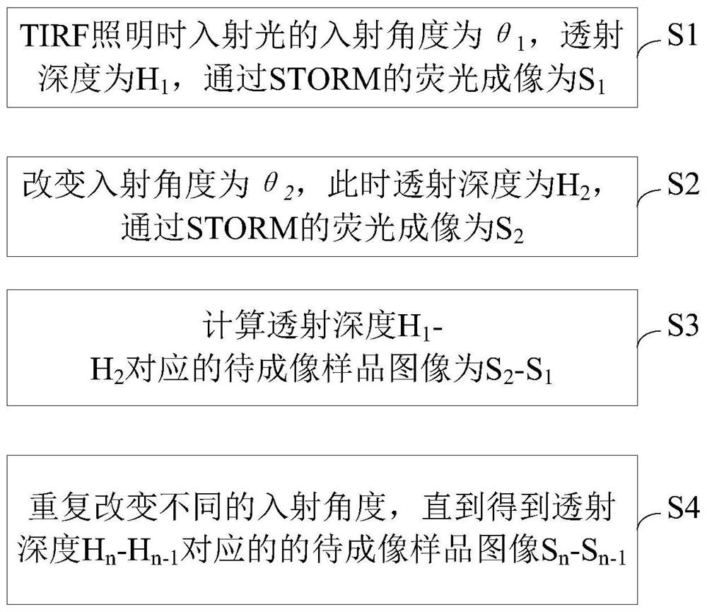
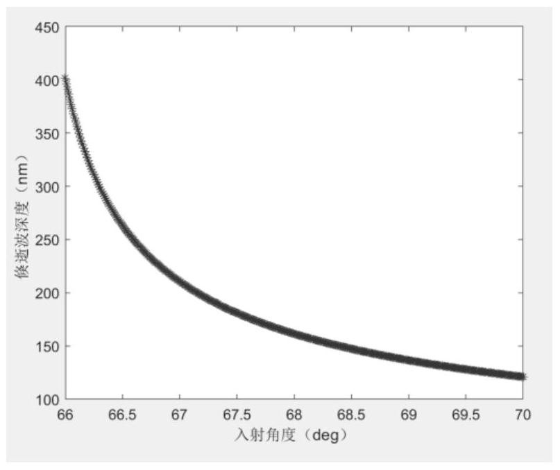
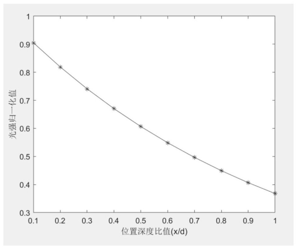
[0040] A depth imaging method of TIRF illumination, comprising: during TIRF illumination, incident light is totally reflected before the sample to be imaged, and evanescent waves are generated, and the generated evanescent waves are transmitted to the sample to be imaged 1013; the incident angle of the incident light is changed , the transmission depth of the evanescent wave changes; when the evanescent waves with different transmission depths are respectively transmitted to the sample to be imaged 1013, the STORM imaging unit images the sample to be imaged 1013, and passes all the images of the sample to be imaged 1013 through a preset image reconstruction algorithm Perform calculations to obtain imaging images of the sample to be imaged 1013 at different depths, thereby realizing depth imaging.

[0041] It should be noted that the preset image reconstruction algorithm...


PUM


Abstract

The invention discloses a depth imaging method and system for TIRF illumination. The method comprises the steps: carrying out total reflection of incident light in front of a to-be-imaged sample during TIRF illumination, generating an evanescent wave, and transmitting the generated evanescent wave to the to-be-imaged sample; changing the incident angle of the incident light, and changing the transmission depth of the evanescent wave; and when the evanescent waves with different transmission depths are irradiated to the to-be-imaged sample, using an STORM imaging unit to image the to-be-imaged sample, calculating all the to-be-imaged sample images through a preset image reconstruction algorithm, acquiring to-be-imaged sample imaging images with different depths, and realizing depth imaging. According to the invention, based on a STORM+TIRF mode, imaging in a certain depth direction is realized through different TIRF illumination.

Description

technical field [0001] The invention relates to the technical field of microscopic imaging, in particular to a depth imaging method and system for TIRF illumination. Background technique [0002] STORM belongs to the field of microscopy imaging. Its principle is that when light is incident on cells with fluorescent staining, the cells will emit random fluorescent flashes. Through multiple imaging, the fluorescent flashing point at each position can be finally obtained, and the position of the flashing point is the position point of the cell. When the light is irradiated on the cells, because of the random flickering of the fluorescence, after one flickering, the position of each flickering point can be finally obtained, and images of different positions of the cells can be obtained. That is, when imaging fluorescent cells, the flickering points are reconstructed through pictures of fluorescent molecules flickering randomly over a period of time to achieve super-resolution i...

Claims


Application Information

Patent Timeline
IPC IPC(8): G01N21/01G01N21/64
CPCG01N21/01G01N21/6402G01N21/6486
Inventor 杨乐宝王宏达
Owner 广东粤港澳大湾区黄埔材料研究院
Why Eureka
Try Eureka