Emission module, depth sensor and electronic equipment

A technology of modules and light-emitting components, applied in the field of emission modules, depth sensors, and electronic equipment, can solve the problems of the limited field of view of emission modules and the inability of depth sensors to achieve depth imaging with a large field of view, so as to achieve a large angle of view. The effect of long-distance depth imaging

Active Publication Date: 2020-11-10
GUANGDONG OPPO MOBILE TELECOMM CORP LTD
View PDF19 Cites 0 Cited by
  • Summary
  • Abstract
  • Description
  • Claims
  • Application Information

AI Technical Summary

Problems solved by technology

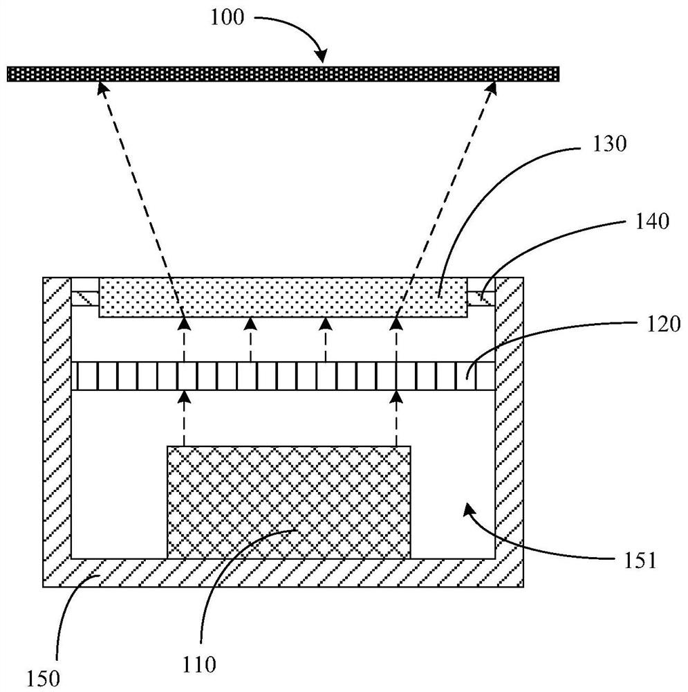
[0004] The purpose of the present disclosure is to provide a transmitting module, a depth sensor, and electronic equipment, so as to overcome at least to a certain extent the problem that the depth sensor cannot achieve depth imaging with a large field of view due to the limited field of view of the depth sensor transmitting module. question

Method used


Image

  • Emission module, depth sensor and electronic equipment
  • Emission module, depth sensor and electronic equipment
  • Emission module, depth sensor and electronic equipment

Examples


Embodiment Construction

[0027] Example embodiments will now be described more fully with reference to the accompanying drawings. Example embodiments may, however, be embodied in many forms and should not be construed as limited to the embodiments set forth herein; rather, these embodiments are provided so that this disclosure will be thorough and complete, and will fully convey the concept of example embodiments to those skilled in the art. The same reference numerals in the drawings denote the same or similar structures, and thus their detailed descriptions will be omitted.

[0028] Although relative terms such as "upper" and "lower" are used in this specification to describe the relative relationship of one component of an icon to another component, these terms are used in this specification only for convenience, for example, according to the description in the accompanying drawings directions for the example described above. It will be appreciated that if the illustrated device is turned over so...


PUM


Abstract

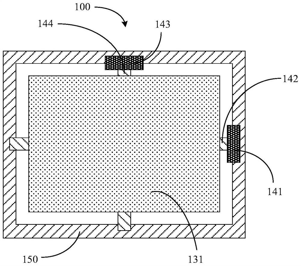
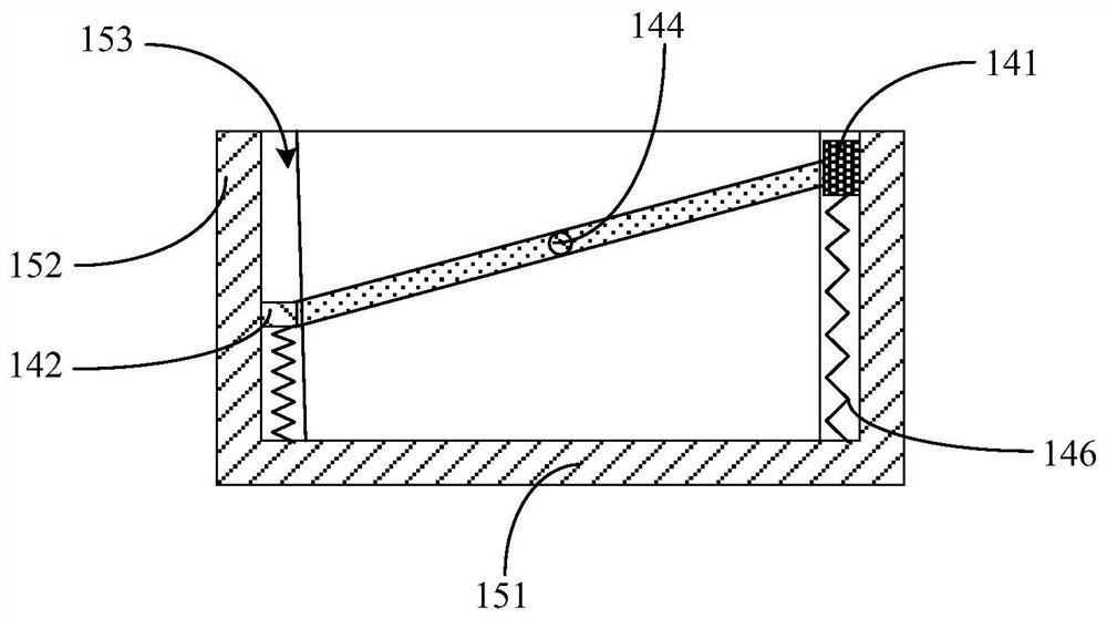
The invention relates to an emission module, a depth sensor and electronic equipment, the emission module comprises a light emitting assembly, an optical lens and an adjusting assembly, and the repeated light emitting assembly is used for providing a light source; the optical lens is arranged on the light-emitting side of the light-emitting assembly. the adjusting assembly is connected with the optical lens, and the adjusting assembly is used for adjusting the relative position relation between the optical lens and the light-emitting assembly so as to adjust the propagation direction of lightprovided by the light-emitting assembly. The field angle of the depth sensor can be increased.

Description

technical field [0001] The present disclosure relates to the technical field of electronic equipment, and in particular, to a transmitting module, a depth sensor, and electronic equipment. Background technique [0002] In computer vision systems, it is often necessary to obtain depth images in different application scenarios, and then perform three-dimensional distance measurement. For example, depth measurement is required in applications such as indoor mapping or navigation. At present, depth images can be obtained through time-of-flight technology, and three-dimensional ranging can be performed based on depth images. However, in practical applications, due to the limited field of view of the depth sensor transmitter module, the depth sensor cannot achieve long-distance and large field of view depth imaging. [0003] It should be noted that the information disclosed in the above background section is only for enhancing the understanding of the background of the present d...

Claims


Application Information

Patent Timeline
IPC IPC(8): G02B27/10G02B26/08G01S7/481G01S17/894
CPCG02B27/10G02B26/08G02B26/0833G02B27/1086G01S17/894G01S7/4815
Inventor 张学勇
Owner GUANGDONG OPPO MOBILE TELECOMM CORP LTD
Why Eureka
Try Eureka