a light sheet microscope

A microscope and light sheet technology, applied in the field of microscopy, can solve problems such as inconvenience, thickened light sheet, and beam wavefront distortion

Active Publication Date: 2021-03-02
GUANGZHOU INST OF BIOMEDICINE & HEALTH CHINESE ACAD OF SCI
View PDF17 Cites 0 Cited by
  • Summary
  • Abstract
  • Description
  • Claims
  • Application Information

AI Technical Summary

Problems solved by technology

[0003] Traditional light sheet microscopes have the limitation of insufficient penetration depth for turbid samples
When the excitation beam is focused on a biological sample with insufficient transparency, the beam will produce wavefront distortion, which will cause the light sheet to become thicker, reduce the resolution and contrast of the image, and thus reduce the penetration depth of illumination
The existing practice is that when imaging the depth of a turbid sample, it is necessary to pre-transparify the sample, which will not only cause certain damage to the sample, but also be inconvenient

Method used


Image

  • a light sheet microscope
  • a light sheet microscope
  • a light sheet microscope

Examples


Embodiment 1

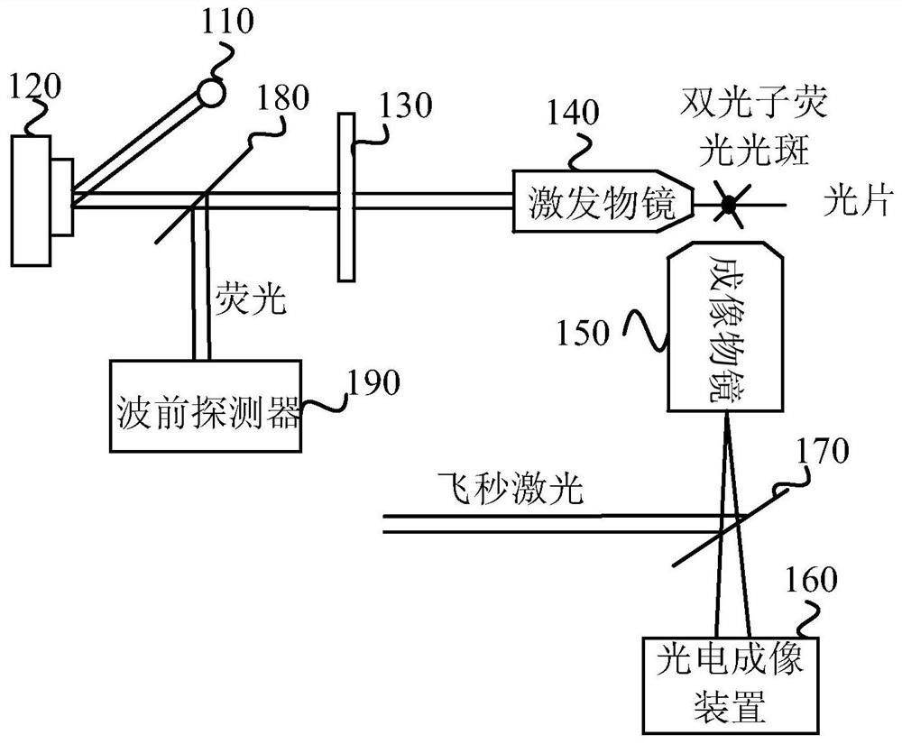
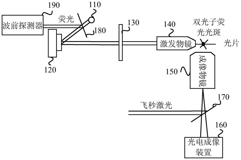
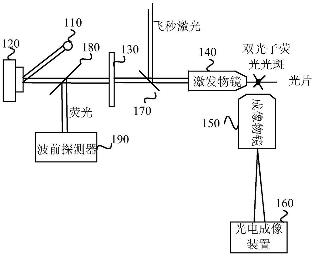
[0034] figure 1 It is a schematic structural diagram of a light-sheet microscope provided in Embodiment 1 of the present invention, and the light-sheet microscope can realize deep imaging of turbid samples. Such as figure 1 As shown, the light sheet microscope includes: a laser light source 110, a light wave phase adjuster 120, a light sheet generating device 130, an excitation objective lens 140, an imaging objective lens 150, a photoelectric detection device 160, a first beam splitter 170, a second beam splitter 180 and Wavefront detector 190 .

[0035] The laser light source 110 is used to generate laser beams. The light wave phase adjuster 120 is used for receiving the laser beam generated by the laser light source 110 and adjusting the phase of the laser beam. The optical sheet generating device 130 is configured to receive the laser beam emitted by the optical wave phase adjuster 120 and shape the laser beam into an optical sheet. The excitation objective lens 140 is...

Embodiment 2

[0054] Figure 5 A schematic structural diagram of a light sheet microscope provided in Embodiment 2 of the present invention, as a further description of the above embodiment, as shown in Figure 5 As shown, the light sheet microscope includes: a laser light source 201, a spatial light modulator 202, a first lens 203, a mirror 204, a second lens 205, an X-axis vibrating mirror 206, a third lens 207, a fourth lens 208, and a Y Axis galvanometer 209, fifth lens 210, sixth lens 211, excitation objective lens 212, imaging objective lens 213, photodetection device 214, first beam splitter 215, second beam splitter 216, wavefront detector 217 and relay lens 218 .

[0055]In this implementation, the working process of the light sheet microscope can be that the laser beam generated by the laser light source 201 enters the spatial light modulator 202, enters the first lens 203 after the phase is modulated by the spatial light modulator 202, and converges through the first lens 203 A...


PUM


Abstract

The embodiments of the invention disclose a light-sheet microscope. The light-sheet microscope of the invention comprises a laser light source, a light wave phase adjuster for adjusting the phase of alaser beam, a light sheet generating device used for receiving the laser beam emitted by the light wave phase adjuster and shaping the laser beam into a light sheet, an excitation objective lens usedfor coupling the light sheet to a sample to excite the sample to generate fluorescence, an imaging objective lens used for collecting and concentrating the fluorescence generated by the excited sample, a photoelectric detection device used for imaging the fluorescence, a first beam splitter disposed between the imaging objective lens and the photoelectric detection device, a second beam splitterfor changing the light path of fluorescence emitted by a two-photon fluorescent spot, and a wavefront detector for detecting the wavefront distortion of the fluorescence emitted by the two-photon fluorescent spot. With the light-sheet microscope provided by the embodiments of the invention adopted, the wavefront distortion of the laser light sheet can be corrected, and the deep imaging of a turbidsample can be realized.

Description

technical field [0001] Embodiments of the present invention relate to the technical field of microscopes, and in particular to a light sheet microscope. Background technique [0002] The imaging method of the light sheet microscope is to select the illumination focal plane for imaging. This method can avoid exciting the sample outside the focal plane, so that the image is not disturbed by the out-of-focus signal, thereby realizing optical section tomography. Since the excited plane of the sample is the focal plane during imaging and will not affect other parts of the sample, light sheet microscopy can minimize photobleaching and photodamage, which is conducive to long-term imaging of living cells. [0003] Traditional light sheet microscopy has the limitation of insufficient penetration depth for turbid samples. When the excitation beam is focused on a biological sample with insufficient transparency, the beam will produce wavefront distortion, which will cause the light sh...

Claims


Application Information

Patent Timeline
Patent Type & Authority Patents(China)
IPC IPC(8): G02B21/06G02B21/00G01N21/01
CPCG01N21/01G02B21/0076G02B21/06
Inventor 张骁骆健忠樊科宋研卢俊麦仕文欧阳瑶张凤香赵洪南张莹董建华秦季生黄海飞
Owner GUANGZHOU INST OF BIOMEDICINE & HEALTH CHINESE ACAD OF SCI
Why Eureka
Try Eureka