Simulation bomb launcher

A technology of a launcher and a simulated bomb, which is applied to weapon accessories, weapon types, weapons without explosives, etc., can solve the problems of hoop adjustment, the base cannot be folded, and it is inconvenient to move, so as to facilitate clamping and reduce flying injuries. risk, the effect of easy folding

Pending Publication Date: 2021-06-01
郑州科斗精准弹射技术有限公司
View PDF1 Cites 2 Cited by
  • Summary
  • Abstract
  • Description
  • Claims
  • Application Information

AI Technical Summary

Problems solved by technology

[0005] In order to solve the technical problems that the base of the existing throwing device cannot be folded and is not easy to move, and the hoop cannot be adjusted for launching tubes of different diameters and simulated

Method used


Image

  • Simulation bomb launcher
  • Simulation bomb launcher
  • Simulation bomb launcher

Examples


Embodiment 1

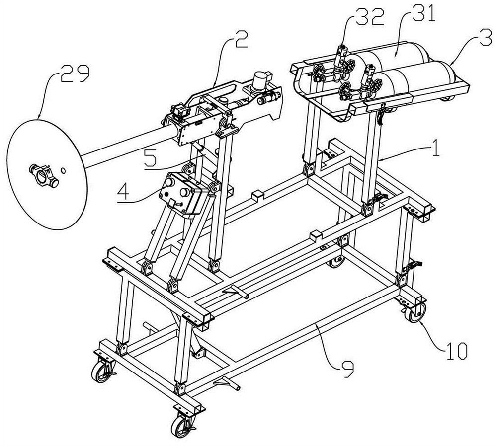
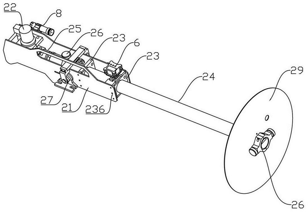
[0065] See attached figure 1 , 3 , the launch tube bracket 21, the solenoid valve 22, the launch tube fastening mechanism 23, the launch tube 24 that matches the simulated bomb (the end of the launch tube 24 away from the launch tube bracket 21 has a pin hole), the air inlet joint 25, the bearing seat 27. After assembling the digital display angle meter 6, the level meter 7, the laser distance meter 8, the gas storage device 3, the support device 1, the controller 4, and the height-increasing device 9, the fastening bolts are connected in the thread adjustment through hole 236 and pushed up. Tighten the second clamping plate 232, thereby fixing the launch tube 24. The baffle plate 29 is sleeved on the inside of the pin hole of the launch tube 24, the simulated projectile is penetrated in the launch tube 24 and the pin hole of the simulated projectile coincides with the pin hole of the launch tube 24, and in the pin hole of the launch tube 24 The first structural form of the ...

Embodiment 2

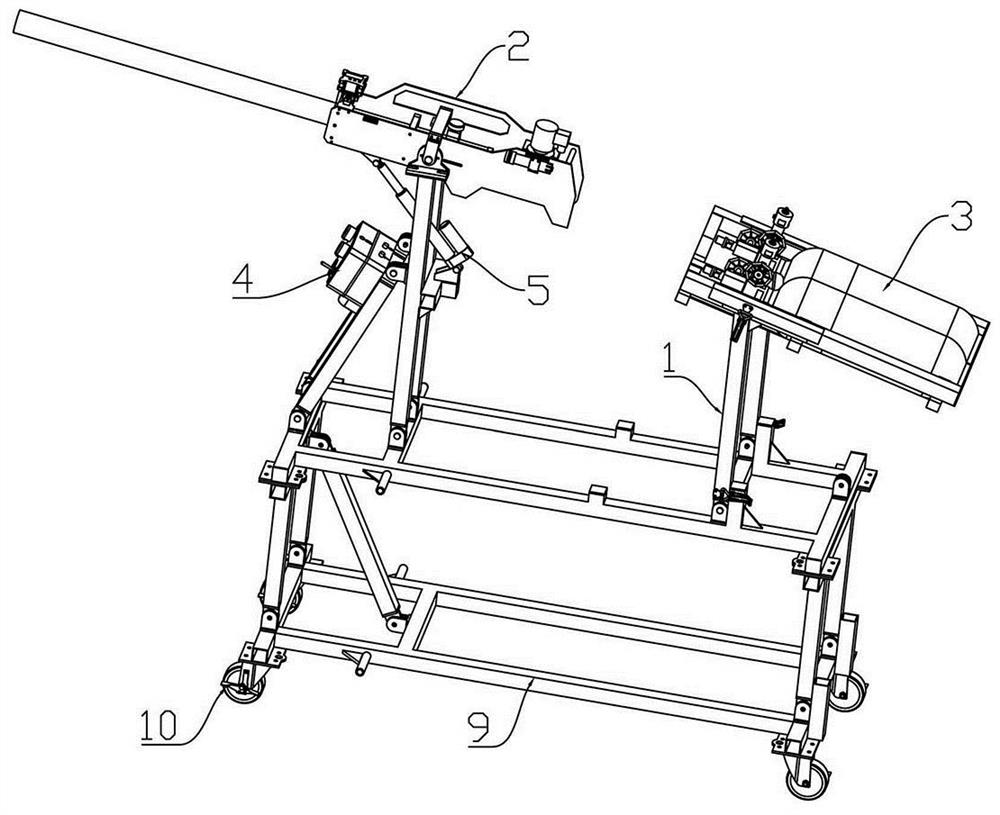
[0067] See attached figure 2 , 5 , the launch tube bracket 21, the solenoid valve 22, the launch tube fastening mechanism 23, the launch tube 24 matching the simulated bomb (the end of the launch tube 24 close to the air inlet joint 25 has a pin hole), the air intake joint 25, the bearing seat 27. After assembling the digital display angle meter 6, the level meter 7, the laser distance meter 8, the gas cylinder group 31, the support device 1, the controller 4, and the height-increasing device 9, fix the inner jacket 28 at intervals on the outer circumference of the launch tube 24 , the spacing distance of each inner jacket 28 is the same as the distance between each launch tube fastening mechanism 23, and the inner jacket 28 on the launch tube 24 is respectively embedded in the first clamping plate 231 and the first clamping plate 231 in the launch tube fastening mechanism 23. In the clamping groove 235 of the second clamping plate 232 , fastening bolts are connected in the ...


PUM


Abstract

The invention relates to the technical field of pneumatic launchers, in particular to a simulation bomb launcher used for pneumatic launching of simulation bombs of multiple specifications. The simulation bomb launcher comprises a supporting device, a throwing device, a gas storage device and a controller. The supporting device comprises a supporting base, a throwing device supporting frame, a gas storage device supporting frame, a supporting limiting mechanism, a supporting connecting plate and a gas storage device bracket. The throwing device comprises a launch canister support, an electromagnetic valve, a launch canister fastening mechanism, a launch canister and a gas inlet connector, one side of a first clamping plate and one side of a cover plate of the launch canister fastening mechanism are fixed to the inner side of a left supporting plate and the inner side of a right supporting plate of the launch canister support correspondingly, a second clamping plate is embedded in the first clamping plate in a sliding manner through a sliding rail and sliding groove mechanism, clamping plate clamping grooves are formed in the first clamping plate and the second clamping plate, and fastening bolts are sequentially connected with the launch canister support and the cover plate and abut against the second clamping plate. The base of the simulation bomb launcher is foldable, and the throwing device can be clamped and adjusted according to launch canisters with different pipe diameters and simulation bombs.

Description

technical field [0001] The invention relates to the technical field of pneumatic launchers, in particular to a simulated projectile launcher for pneumatic launch of multi-standard simulated projectiles. Background technique [0002] Existing launchers for rescue use pneumatic (or hydraulic) energy to accurately launch the payload bomb to the target area, which can complete the launch of the fire extinguishing bomb, and can also provide the required equipment and materials for the personnel in the target area in real time, and can be widely used in lifesaving, Fire fighting occasions. However, the launch distance of existing rescue launchers is small. In order to carry out long-distance launch, it is necessary to improve the adaptability of the launch components and air pressure energy components on the basis of the original launcher, and test the launch distance and launch angle through simulated projectiles. . In addition, after the simulated bomb (throwing bomb) is impro...

Claims


Application Information

Patent Timeline
IPC IPC(8): F41B11/60F41A21/48F41G3/06F41G5/00F41G11/00
CPCF41A21/48F41B11/60F41G3/06F41G5/00F41G11/001
Inventor 梁存真张亚宁王文涛刘救世陈海瑞杨阳孙铭礁周地广
Owner 郑州科斗精准弹射技术有限公司
Why Eureka
Try Eureka