Eureka AIR delivers breakthrough ideas for toughest innovation challenges, trusted by R&D personnel around the world.

Adjusting clamping block structure for automobile tool

A technology for tooling and automobiles, which is applied in the direction of workpiece clamping devices, workbenches, manufacturing tools, etc. It can solve the problems that the direction cannot be changed at will, the clamping block cannot clamp the object, and the clamping block angle is not equal.

Inactive Publication Date: 2021-06-04
杨莉莉
View PDF13 Cites 0 Cited by
  • Summary
  • Abstract
  • Description
  • Claims
  • Application Information

AI Technical Summary

Problems solved by technology

[0006] In order to solve the above-mentioned technical problems, the present invention provides an adjustment clamp block structure for automobile tooling, to solve the problem that most of the existing clamp blocks are installed on the clamping device. During the use of the clamping device, due to the The position of the clamping block cannot change the direction at will, but the position and angle of the object to be clamped are different, so the direction and angle of the device need to be adjusted to clamp the object. If only the direction of the device can be adjusted, it will easily lead to the clamping block on the device. The angle is wrong, so that the clamp block cannot clamp the object

Method used


Image

  • Adjusting clamping block structure for automobile tool
  • Adjusting clamping block structure for automobile tool
  • Adjusting clamping block structure for automobile tool

Examples


Embodiment

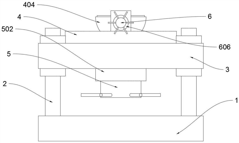
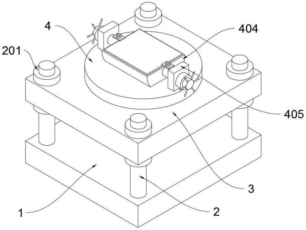
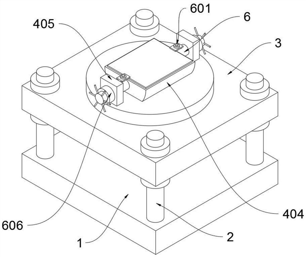
[0034] as attached figure 1 to attach Figure 8 Shown:

[0035] The invention provides an adjusting clip block structure for automobile tooling, which includes a fixed plate 1; left and right mutually symmetrical thread columns 2 are fixedly installed at the front and rear ends of the top of the fixed plate 1; Symmetrical groove; the threaded column 2 includes a bearing ring 201, the upper and lower ends of the four threaded columns 2 are equipped with a circular bearing ring 201, the bottom of the upper end bearing ring 201 is closely attached to the top of the lifting plate 3, and the lower end carries The top of the ring 201 is closely attached to the bottom of the lifting plate 3, and the carrying ring 201 is loosened, and the lifting plate 3 can move up and down to adjust the height, and then the lifting plate 3 is fixed with the carrying ring 201. The lifting plate 3 includes a bearing groove 301 and Rotary groove 302, a ring-shaped bearing groove 301 is opened in the ...


PUM


Abstract

The invention provides an adjusting clamping block structure for an automobile tool, and relates to the technical field of automobile tools. The problems that most existing clamping blocks are installed on a clamping device for use, and in the using process of the clamping device, due to the fact that the positions of the clamping blocks on the clamping device cannot be changed at will, the positions and angles of objects needing to be clamped are different, an object cannot be clamped until the direction and angle of the device are adjusted, and if only the direction of the device can be adjusted, the angle of the clamping blocks on the device is not right, and the clamping blocks cannot clamp the object are solved. The adjusting clamping block structure comprises a fixing plate, wherein threaded columns which are symmetrical left and right are fixedly installed at the front end and the rear end of the top of the fixing plate. According to the adjusting clamping block structure, a base of a clamping device is fixed through two inserting blocks, then a clamping plate is fixed through a hand wheel, after the angle of an adjusting block is adjusted in an adjusting groove, an elastic ring is tightened to fix the adjusting block, and at the moment, the clamping device on the adjusting block can clamp and fix an object.

Description

technical field [0001] The invention relates to the technical field of automobile tooling, and more specifically relates to an adjusting clip block structure for automotive tooling. Background technique [0002] In the field of mechanical production and processing, "tooling" refers to the production process equipment: it refers to the general term for various tools used in the manufacturing process. Including tools / fixtures / molds / measuring tools / checking tools / auxiliary tools / fitter tools / positioning tools, etc. [0003] There are many existing adjusting clamping block structures such as a clamping and adjusting device for automobile pipeline processing in the patent application CN201910746548.3. The present invention relates to the technical field of automobile processing equipment. The left side of the upper bottom plate is vertically fixed with a support mechanism. The pipeline is movable in the middle of the support mechanism; the front and rear sides between the driven...

Claims


Application Information

Patent Timeline
Patent Type & Authority Applications(China)
IPC IPC(8): B25H1/10B25B11/00
CPCB25H1/10B25B11/00
Inventor 杨莉莉
Owner 杨莉莉
Why Eureka
Eureka Blog
Learn More