

Compound, light extraction material and organic electroluminescent device
A compound, light extraction technology
- Summary
- Abstract
- Description
- Claims
- Application Information
AI Technical Summary
Problems solved by technology
Method used
Image

Examples
Embodiment 1
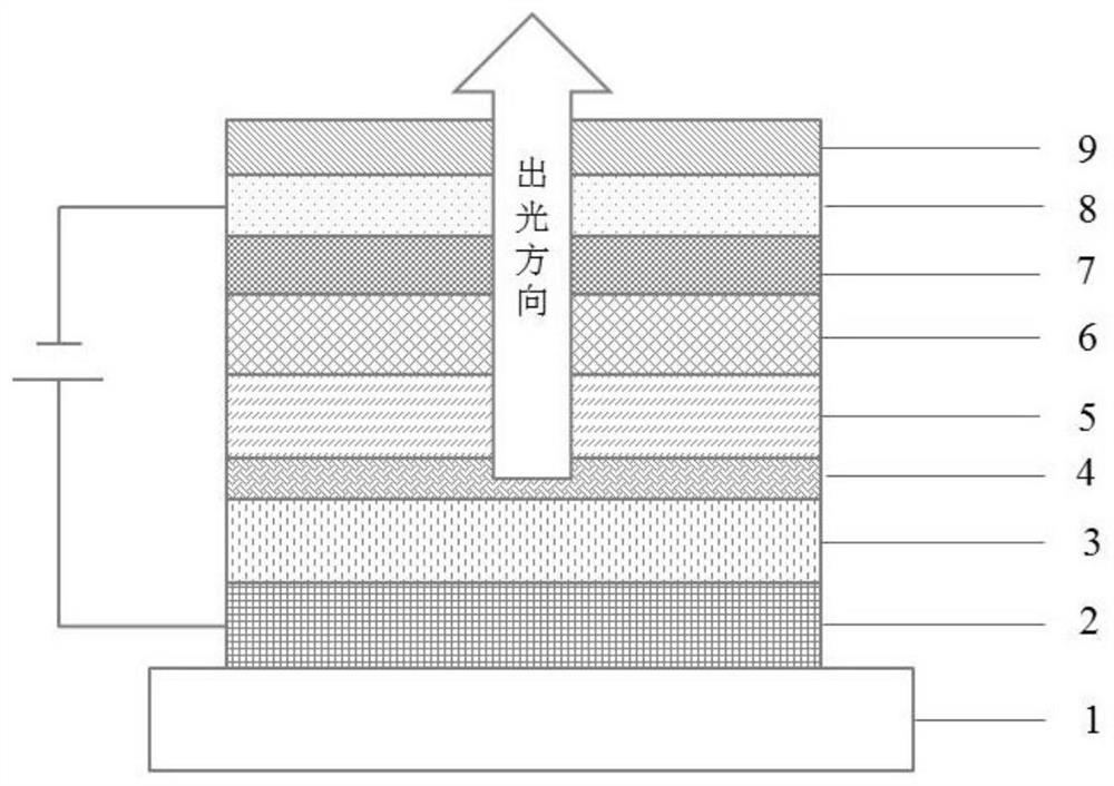
[0170] A reflective anode electrode is set on the glass substrate, the anode electrode is an ITO electrode, and the thickness of the electrode is 130nm;
[0171] Then, vacuum-deposit a hole injection layer with a thickness of 10 nm on the anode electrode. The material of the hole injection layer is HT-21 and a p-type dopant p-3 with a mass ratio of 3%, wherein the evaporation rate is 0.1 nm / s, the selected hole injection layer material and p-type dopant are the following materials:
[0172]
[0173] Then, a hole transport layer of 112 nm is vacuum-evaporated on the hole injection layer, the material of the hole transport layer is the above-mentioned HT-32, wherein the evaporation rate is 0.1 nm / s;
[0174] Then, on the hole transport layer, the luminescent layer is vacuum-evaporated. The luminescent layer includes the host material BH-37 and the luminescent dye BD05. It is evaporated by multi-source co-evaporation, wherein the evaporation of the host material BH-37 is adjus...
Embodiment 2-5
[0183] Except that the thickness of the light extraction layer was changed as shown in Table 1, the rest was the same as in Example 1.
Embodiment 6
[0185] Except that the luminescent host material and the luminescent dye were replaced by GPH-77 and GD05, the rest was the same as that of Example 1.
[0186]
[0187] The organic electroluminescence device of this embodiment emits green light.
PUM
| Property | Measurement | Unit |
|---|---|---|
| thickness | aaaaa | aaaaa |
| thickness | aaaaa | aaaaa |
| thickness | aaaaa | aaaaa |
Abstract
Description
Claims
Application Information