
Continuously variable transmission

A technology of continuously variable transmission and device, applied in the direction of transmission, friction transmission, belt/chain/gear, etc., can solve the problems of limiting the usable range of the continuously variable transmission and damaging the efficiency.

Pending Publication Date: 2021-07-23
엘타트에스알엘
View PDF8 Cites 0 Cited by
  • Summary
  • Abstract
  • Description
  • Claims
  • Application Information

AI Technical Summary

Problems solved by technology

[0010] Understandably, this flaw hurts efficiency and limits the CVT's usable range

Method used


Image

  • Continuously variable transmission
  • Continuously variable transmission
  • Continuously variable transmission

Examples


Embodiment Construction

[0039] Before explaining the various embodiments of the invention in detail, it should be clarified that the invention is not limited in application to the structural details and configurations of components set forth herein or shown in the drawings. The invention is capable of other embodiments, and indeed of being practiced or carried out in various ways. It should also be understood that the phraseology and terminology have a descriptive purpose and should not be construed as limiting.

[0040] The invention can be realized according to various alternative construction solutions having different geometrical designs but achieving the same type of operation.

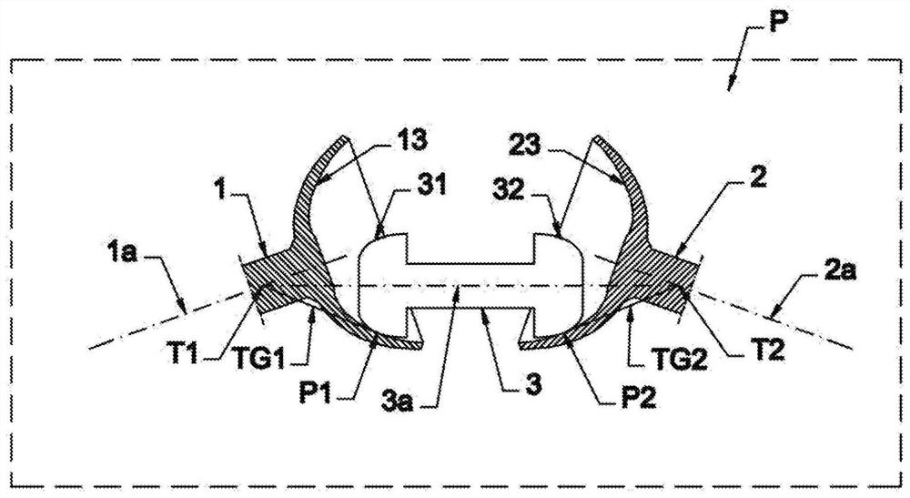
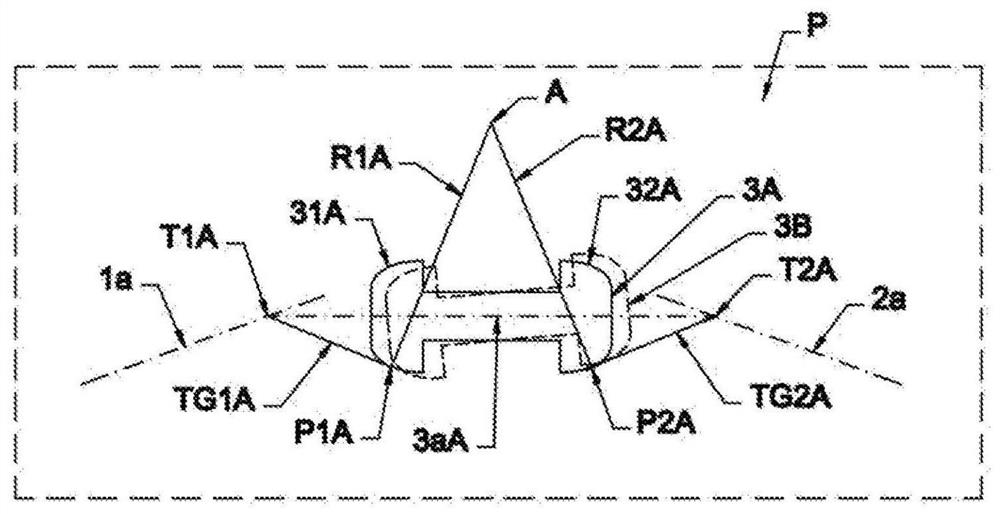
[0041] For example, refer to Figure 1A and Figure 1B, the continuously variable transmission comprises a first main shaft 1 and a second main shaft 2 having respective axes of rotation 1a, 2a fixed and coplanar with respect to a reference plane P.

[0042] Said spindles 1 , 2 are each provided with a main rolling su...


PUM


Abstract

A continuously variable transmission comprises first and second main shafts (1, 2) and at least one auxiliary shaft (3) rotatable around a rotation axis (3a) and interposed between the main shafts (1, 2). The auxiliary shaft (3) is provided with two secondary roll surfaces (31, 32) each shaped as a solid of revolution and placed in contact, each one, with a respective primary roll surface (13, 23) of the main shafts (1, 2), wherein the roll surfaces (13, 23, 31, 32) are so shaped that the straight lines (TG1, TG2) tangential thereto in the contact points between the auxiliary shaft (3) and the main shafts (1, 2) pass through two distinct intersection points (T1, T2) between the axes of said shafts (1, 2, 3).

Description

technical field [0001] The present invention is generally in the field of motion transmission systems; in particular, the invention relates to a continuous gearbox for transferring motion between two shafts. Background technique [0002] In mechanical applications, there is a widespread need to construct a variator, ie a device that allows connecting two axes of rotation so as to have a variable transmission ratio available. [0003] The device is usually arranged between a motor and a user, and it is used in many fields from road transportation to various types of industries. [0004] In many applications it is preferable to be able to change the gear ratio continuously (in the sense that all intermediate gear ratios between the maximum and minimum values ​​can be obtained). Hereinafter, a device providing this feature will be defined as a "continuously variable transmission". [0005] There are currently different types of continuously variable transmissions. [0006] A...

Claims


Application Information

Patent Timeline
Patent Type & Authority Applications(China)
IPC IPC(8): F16H15/30
CPCF16H15/30
Inventor 卡洛·恰韦斯保罗·恰韦斯
Owner 엘타트에스알엘
Learn More