Induction appliance with thickness-adjustable occlusal pad in molar area
An appliance and occlusal pad technology, which is applied in the field of orthodontic treatment, can solve the problems of unadjustable thickness, inability to effectively control the vertical growth of the dental area, and inability to improve the vertical developmental deformity of the teeth and jaws, so as to reduce the malocclusion. problems, cost savings, and the effect of reducing waste of resources
- Summary
- Abstract
- Description
- Claims
- Application Information
AI Technical Summary
Problems solved by technology
Method used
Image
Examples
Embodiment 1
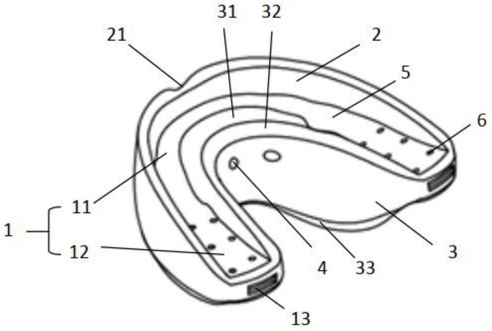
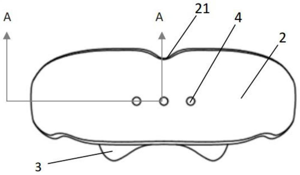
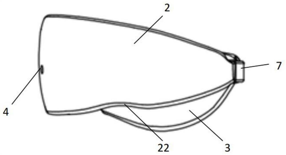
[0046] Such as figure 1 , image 3 As shown, the induction appliance with adjustable thickness of the occlusal pad in the molar area includes a U-shaped occlusal pad 1, and the occlusal pad 1 includes an anterior occlusal pad 11 and a molar occlusal pad 12. The outer surface of the occlusive pad 1 The edges extend upwards and downwards to form a lip and cheek barrier 2 , and the inner edges of the pad 1 extend upwards and downwards to form a tongue barrier 3 . The occlusal pad 1, the lip-cheek pad 2, and the tongue pad 3 together form an upper and lower integrated induction appliance adapted to the occlusion of the teeth. The adjustment pad 7 in the receiving groove 13.
[0047] The accommodating groove 13 and the adjusting pad 7 accommodated in the accommodating groove 13 are detachably connected for adjusting the thickness of the occlusal pad 12. When the adjusting pad 7 is accommodated in the accommodating groove 13, the The thickness of the occlusal pad 12 can be varied...
Embodiment 2
[0082]The present invention provides an induction appliance with an adjustable molar pad thickness. Embodiment 2 is similar in structure to Embodiment 1, as Figure 6 As shown, the difference between this embodiment and Embodiment 1 is that the long end surfaces 133 of the accommodation grooves on both sides of the accommodation groove 13 include uneven wavy cut surfaces, which are used to fix the adjusting pad 7 in the accommodation groove. 13 The role of the inner position to prevent falling off.
[0083] Specifically, the long end surface 133 of the accommodation groove is set as a wave-like plane at one end adjacent to the first transverse end surface 131 of the accommodation groove, and the long end surface 133 of the accommodation groove is arranged at one end adjacent to the second transverse end surface 132 of the accommodation groove. Set it as a smooth plane to avoid excessive surface resistance of the long end surface 133 of the accommodation groove 13 when placing ...
Embodiment 3
[0087] The present invention provides an induction appliance with adjustable thickness of the molar pad. Embodiment 3 is similar to Embodiment 1 in structure, as Figure 7 As shown, the difference is that: the two sides of the receiving groove 13 include protrusions containing groove limit angles 134 for limiting the position of the adjusting pad 7 and preventing the adjusting pad 7 from falling out of the receiving groove 13 .
[0088] Specifically, the limiting angle 134 of the accommodation groove is located in the accommodation groove 13, is in a vertical relationship with the long end surface 133 of the accommodation groove, and is not in the same plane as the second transverse end surface 132 of the accommodation groove, and the limiting angle 134 of the accommodation groove is located at The junction between the long end surface 133 of the receiving tank and the second lateral end surface 132 of the receiving tank is adjacent to the second lateral end surface 132 of the ...
PUM
 Abstract
Description
Claims
Application Information
 - R&D
- Intellectual Property
- Life Sciences
- Materials
- Tech Scout
- Unparalleled Data Quality
- Higher Quality Content
- 60% Fewer Hallucinations
Browse by: Latest US Patents, China's latest patents, Technical Efficacy Thesaurus, Application Domain, Technology Topic, Popular Technical Reports.
© 2025 PatSnap. All rights reserved.Legal|Privacy policy|Modern Slavery Act Transparency Statement|Sitemap|About US| Contact US: help@patsnap.com


