
Automatic blow-and-suck dust capture removal system based on low-position dust of underground mine roadway

A dust removal system and dust technology, applied in the fields of dust prevention, mining equipment, chemical instruments and methods, etc., can solve the problems of the underground environment, the adverse effects of the life of precision equipment and equipment on the health of engineers, and the difficulty of effectively removing dust. Sustainability of recycling, improved functional usability, improved effect of filtering sedimentation

Inactive Publication Date: 2021-11-26
潍坊智汇贻成科技创新有限公司
View PDF0 Cites 0 Cited by
  • Summary
  • Abstract
  • Description
  • Claims
  • Application Information

AI Technical Summary

Problems solved by technology

[0005] For this reason, the present invention provides an automatic blowing, suction, and collection dust removal system based on low-level dust in underground mine roadways to solve the problem that the dust on the ground of mine roadways in the prior art is difficult to be effectively removed, and the ground dust will be used as the source of dust. The technical problem of blowing up the suspension, which will adversely affect the downhole environment, the life of precision equipment and equipment, and the health of engineers

Method used


Image

  • Automatic blow-and-suck dust capture removal system based on low-position dust of underground mine roadway
  • Automatic blow-and-suck dust capture removal system based on low-position dust of underground mine roadway
  • Automatic blow-and-suck dust capture removal system based on low-position dust of underground mine roadway

Examples


Embodiment Construction

[0057] The implementation mode of the present invention is illustrated by specific specific examples below, and those who are familiar with this technology can easily understand other advantages and effects of the present invention from the contents disclosed in this description. Obviously, the described embodiments are a part of the present invention. , but not all examples. Based on the embodiments of the present invention, all other embodiments obtained by persons of ordinary skill in the art without making creative efforts belong to the protection scope of the present invention.

[0058] Terms such as "upper", "lower", "left", "right", and "middle" quoted in this specification are only for convenience of description, and are not used to limit the scope of implementation of the present invention. The change or adjustment of the relationship shall also be regarded as the applicable scope of the present invention without substantive change in the technical content.

[0059] ...


PUM


Abstract

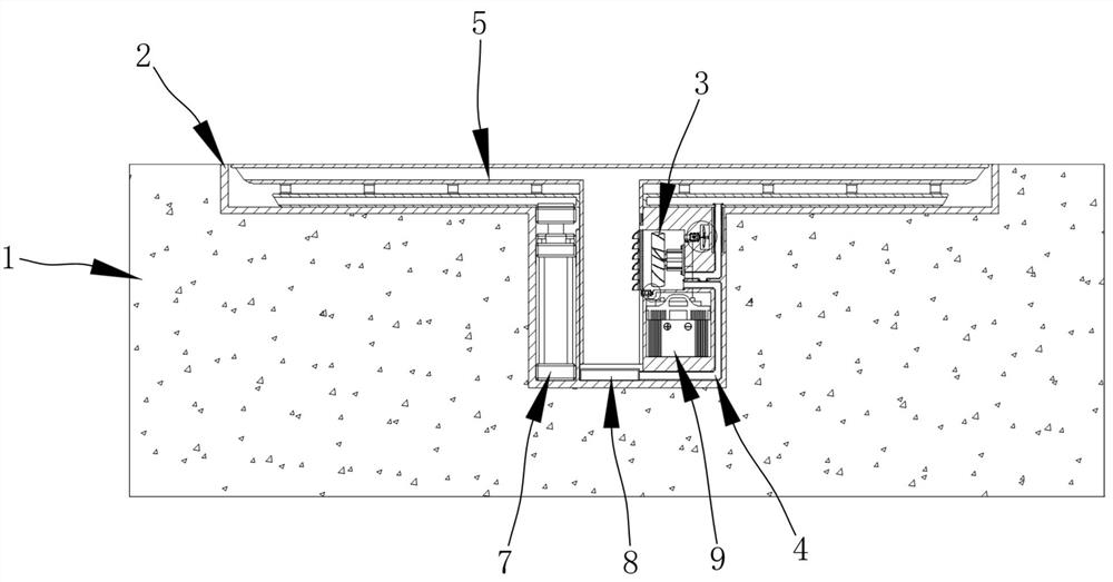
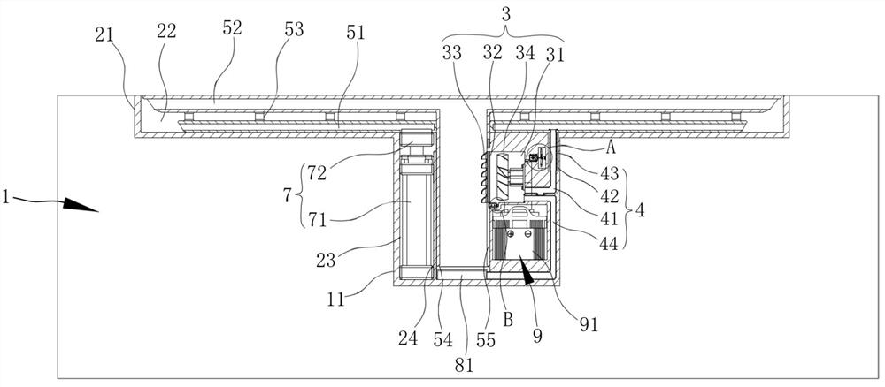
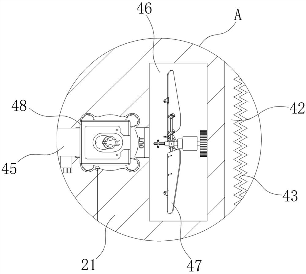
The invention discloses an automatic blow-and-suck dust capture removal system based on low-position dust of an underground mine roadway, and belongs to the technical field of mine dust removing systems. The system consists of a positioning mounting structure, a blowing and sucking driving structure, an airflow transmission pipeline, a blowing and capturing structure, a lifting module, a dust storage structure and an electric control structure, wherein the blowing and sucking driving structure is used for generating blowing airflow and adsorption airflow respectively, the blowing airflow can slightly blow dust on a roadway pavement through the blowing and capturing structure after being conducted through the airflow conveying pipeline, and the adsorption airflow can synchronously utilize the blowing and capturing structure to adsorb and capture the blown ground dust; the adsorbed and captured dust gas is filtered and settled and then is conveyed to the dust storage structure. The electric control structure is matched with the lifting module, so that the height of the blowing and capturing structure can be adjusted, and the blowing and sucking position of the blowing and capturing structure can move outwards or inwards along with the change of the height in combination with the oblique annular blowing and sucking effect generated by the blowing and capturing structure. Therefore, dust removal in the ground within a specific range is realized.

Description

technical field [0001] The invention relates to the technical field of mine dust removal systems, in particular to an automatic blowing, suction, and collection dust removal system based on low-level dust in underground mine lanes. Background technique [0002] At present, a large amount of dust is generated in the mine bottom roadway during the process of digging rock walls and moving machinery, and the dust in the mine roadway usually falls to the ground due to its own gravity after drifting in the air for a period of time. [0003] Since the dust removal equipment in the prior art only focuses on removing the dust floating in the air, it is difficult for the dust falling to the ground to be effectively removed by the prior art. As the engineers walk back and forth and move the equipment during the operation, the dust on the ground is easily re-blown and suspended, which will have a negative impact on the underground environment, the life of precision equipment and the hea...

Claims


Application Information

Patent Timeline
IPC IPC(8): B01D50/00E21F5/00
CPCE21F5/00
Inventor 林伟磊
Owner 潍坊智汇贻成科技创新有限公司
Learn More