Glass crusher

A crusher and glass technology, which is applied in the direction of solid separation, filter screen, grille, etc., can solve the problems of the personal safety of the staff, affect the filtration of glass debris, and the crushing roller can not be broken effectively, so as to achieve the effect of convenient collection

Pending Publication Date: 2021-12-24
广东明轩实业有限公司
View PDF0 Cites 0 Cited by
  • Summary
  • Abstract
  • Description
  • Claims
  • Application Information

AI Technical Summary

Problems solved by technology

[0003] The glass industry often needs to recycle some waste glass, and glass recycling usually needs to be crushed. The existing crushers generally crush the glass through crushing rollers, and then the broken glass slag falls into the glass through the filter plate inside the crusher. Inside the collection box, the glass shards are transported away through the collection box, but when the filter plate is filtering the glass slag, the mesh inside the filter plate is easily blocked by the glass shards, which will affect the later broken glass shards. The filtration of crumbs, and some large pieces of glass falling on the filter plate are located under the crushing roller, so that the crushing roller cannot effectively crush them, which in turn affects the crushing operation
[0004] In addition, there is no other blocking device at the feed port of the general crusher, so that the glass fragments inside the crusher often splash out of the crushing device during use, so that when the staff put in the glass, the splashed glass fragments Chips have an impact on the personal safety of the staff, and some will install baffles, but when the glass is added, the feed port will be completely exposed, so that the staff still has the danger of being injured, making the working environment of the staff a potential safety hazard , in view of the above situation, we propose a glass breaker

Method used


Image

  • Glass crusher
  • Glass crusher
  • Glass crusher

Examples


Embodiment 1

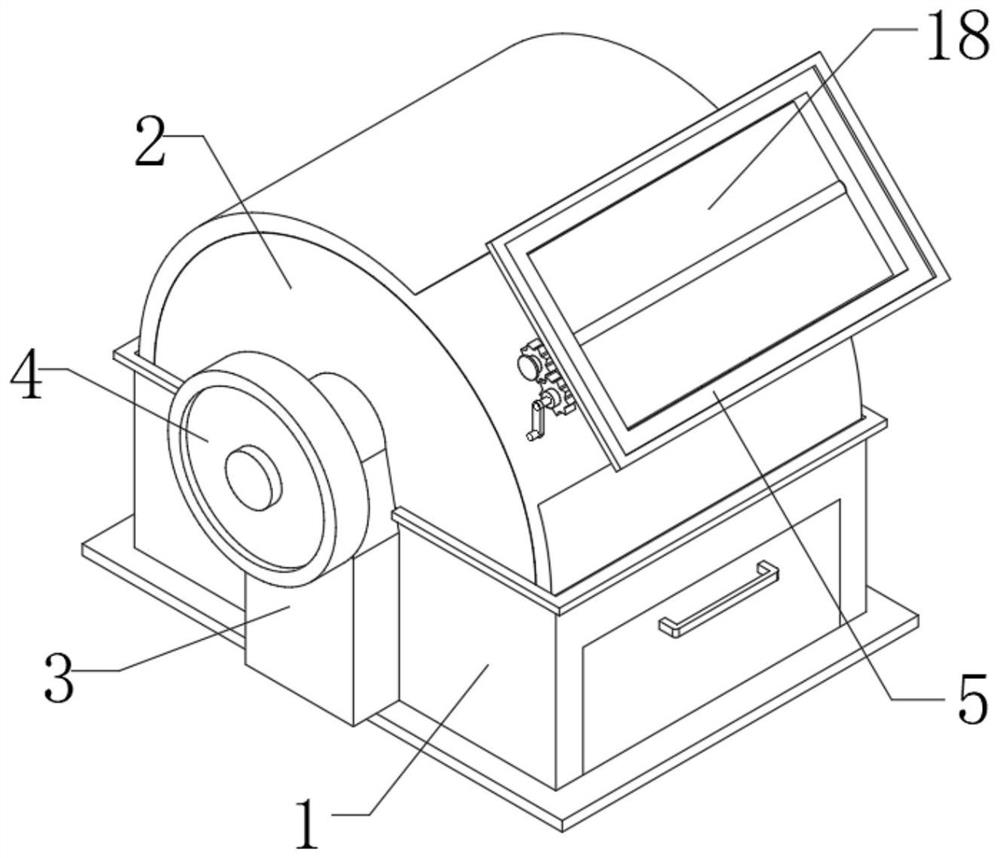
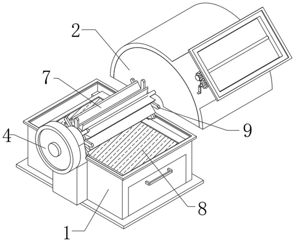
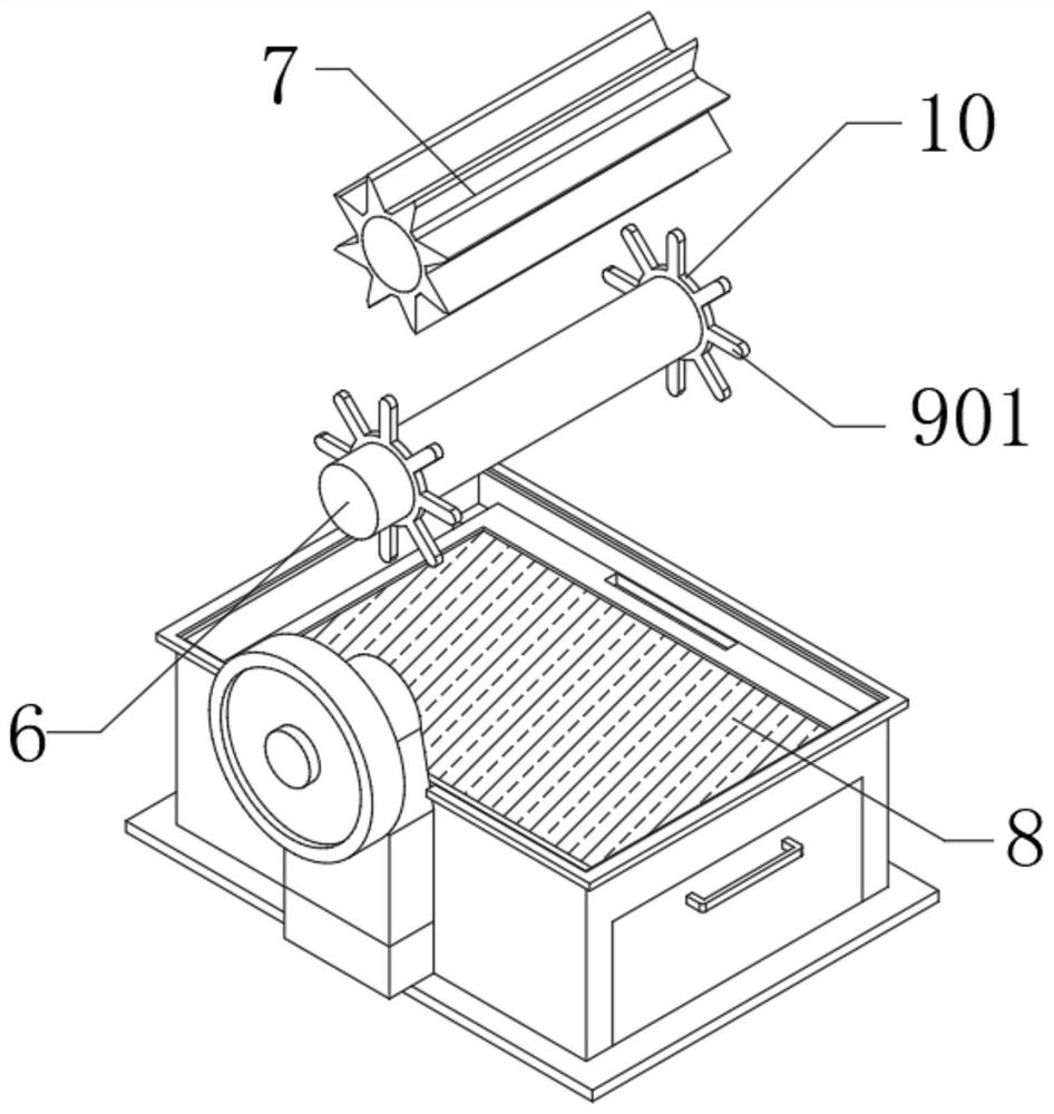
[0042] Such as Figure 1-9 The shown glass crusher includes a crusher main body 1, the upper surface of the crusher main body 1 is equipped with a casing 2, one side of the crusher main body 1 is fixedly installed with a fixed seat 3, and one side of the fixed seat 3 is rotatably connected with a The connecting column 6 is equipped with a motor 4 on one side of the connecting column 6, and the outer surface of the connecting column 6 is fixedly sleeved with a crushing roller 7, and the outer surface of the casing 2 is provided with a feed port 5, and the inside of the feed port 5 is equipped with a baffle 18;

[0043] The shaking mechanism 9 is installed inside the main body 1 of the crusher. The shaking mechanism 9 includes a push plate 901. Multiple groups of push plates 901 are assembled on the outer surface of the connecting column 6. The inside of the main body 1 of the crusher is equipped with a filter plate 8. One end of multiple sets of push plates 901 is rotatably co...

Embodiment 2

[0047] Such as Figure 1-9 A glass breaker is shown, based on the description in Embodiment 1, one side of the feed port 5 is rotatably connected with a fixed rod 19, and a connecting hole 20 is opened inside the baffle plate 18, and the baffle plate 18 is fixed through the connecting hole 20. Be connected to the outer surface of fixed rod 19, one side of feeding port 5 is equipped with rotating mechanism 21, and rotating device 21 comprises first gear 211, threaded rod 212 and second gear 213, and fixed rod 19 extends out of feeding port 5 The outer surface of one end is fixedly sleeved with a first gear 211, one side of the case 2 is rotatably connected with a threaded rod 212, the threaded rod 212 is located on one side of the fixed rod 19, and the outer surface of the threaded rod 212 is fixedly sleeved with a second gear 213 , the first gear 211 and the second gear 213 are meshed, and a handle 22 is fixedly installed on one side of the threaded rod 212 .

[0048] First, ...

Embodiment 3

[0051] Such as Figure 1-9 Shown is a glass crusher, based on the description in Embodiments 1 and 2, the side wall of the crusher main body 1 is fixedly equipped with a bearing plate 13, and the filter plate 8 is slidably connected to the upper surface of the bearing plate 13, and the length of the filter plate 8 is Less than the length of the bearing plate 13, the length of the bearing plate 13 is equal to the length of the main body 1 of the crusher, and the lower surface of the two sets of bearing plates 13 is slidingly connected with the collection box 11, the collection box 11 is located directly below the filter plate 8, the collection box 11 The two sides of the crusher are equipped with spherical rods, and the spherical rods are movably clamped in the inside of the main body 1 of the crusher.

[0052] The collection box 11 slides to the inside of the crusher main body 1 through the hole on one side of the crusher main body 1, and is located directly below the filter p...


PUM


Abstract

The invention discloses a glass crusher, and relates to the field of glass processing. The glass crusher comprises a crusher body. A housing is assembled on the upper surface of the crusher body, a connecting column is rotationally connected to one side of the crusher body, a crushing roller is installed on the outer surface of a motor, a feeding port is formed in the outer surface of the housing, and a baffle is assembled in the feeding port. When the glass crusher is in use, the motor drives the crushing roller installed on the outer surface of a connecting column to rotate, in the rotating process of the connecting column, a push plate installed on the outer surface of the connecting column rotates inside a fixed groove, and then a filter plate is pushed to reciprocate in the crusher, so that a filter plate is shaken; and furthermore, glass fragments in the meshes of the filter plate fall into a collecting box below, so that it happens less that the meshes of the filter plate are blocked by the glass fragments, and then filtering of the glass fragments is influenced.

Description

technical field [0001] The invention relates to the technical field of glass processing, in particular to a glass breaker. Background technique [0002] Glass is an amorphous inorganic non-metallic material. It is generally made of a variety of inorganic minerals as the main raw material and a small amount of auxiliary raw materials. Its main components are silicon dioxide and other oxides. It is widely used in buildings to insulate It is a mixture of wind and light, and there are colored glasses mixed with certain metal oxides or salts to show color, and tempered glass made by physical or chemical methods. [0003] The glass industry often needs to recycle some waste glass, and glass recycling usually needs to be crushed. The existing crushers generally crush the glass through crushing rollers, and then the broken glass slag falls into the glass through the filter plate inside the crusher. Inside the collection box, the glass shards are transported away through the collect...

Claims


Application Information

Patent Timeline
Patent Type & Authority Applications(China)
IPC IPC(8): B02C4/20B02C4/30B02C4/28B02C23/04B02C23/10B07B1/28B07B1/42
CPCB02C4/20B02C4/30B02C4/28B02C23/04B02C23/10B07B1/28B07B1/42B02C2201/06
Inventor 韩炳森
Owner 广东明轩实业有限公司
Why Eureka
Try Eureka