Supercharge Your Innovation With Domain-Expert AI Agents!

Floater based flow control device for gravity intravenous sets

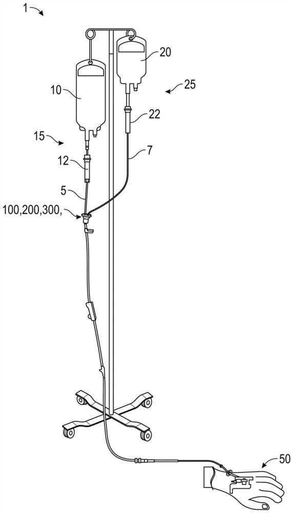
A flow control, fluid technology, used in valve operation/release devices, valve devices, hypodermic devices, etc., to solve problems such as insufficient infusion, patient air embolism, adverse effects, etc.

Pending Publication Date: 2022-01-25
CAREFUSION 303 INC
View PDF0 Cites 0 Cited by
  • Summary
  • Abstract
  • Description
  • Claims
  • Application Information

AI Technical Summary

Problems solved by technology

In addition, underinfusions often occur due to air entering the secondary line, causing some secondary drug to remain in the secondary line (undelivered drug)
Air entering the IV line may have adverse effects such as air embolism in the patient

Method used


Image

  • Floater based flow control device for gravity intravenous sets
  • Floater based flow control device for gravity intravenous sets
  • Floater based flow control device for gravity intravenous sets

Examples


Embodiment Construction

[0026] The detailed description set forth below describes various configurations of the subject technology and is not intended to represent the only configurations in which the subject technology may be practiced. The detailed description includes specific details in order to provide a thorough understanding of the subject technology. Accordingly, dimensions with respect to certain aspects may be provided as non-limiting examples. It will be apparent, however, to one skilled in the art that the subject technology may be practiced without these specific details. In some instances, well-known structures and components are shown in block diagram form in order to avoid obscuring the concepts of the subject technology.

[0027] It should be understood that the present disclosure includes examples of the subject technology and does not limit the scope of the appended claims. Various aspects of the subject technology will now be disclosed in terms of specific but not limiting examp...


PUM


Abstract

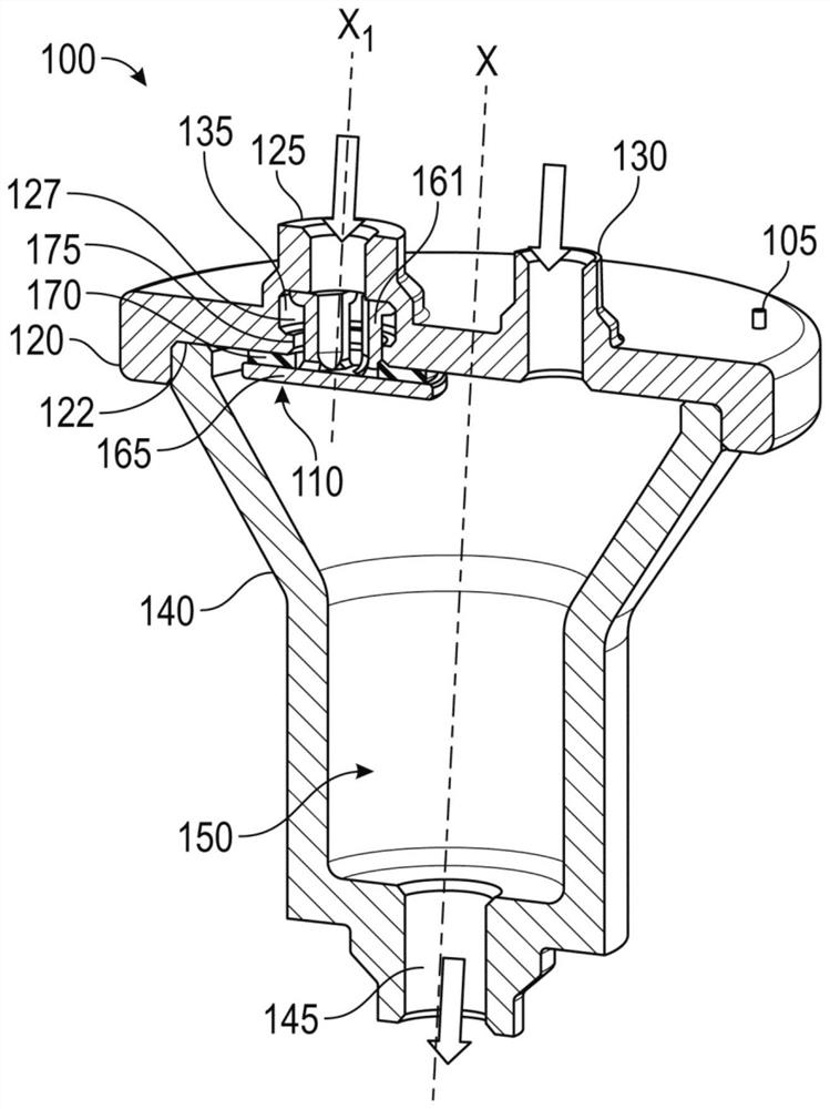
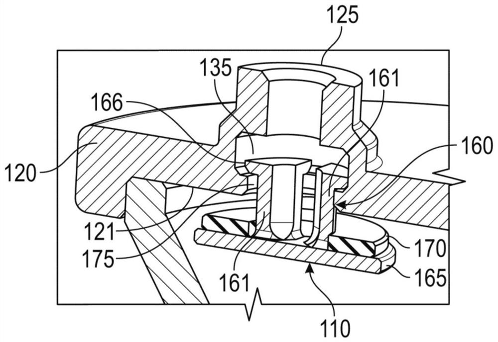
A flow control device includes an upper housing, a lower housing, a chamber interposed between and defined by the upper and lower housings, and a valve member. The upper housing includes a primary inlet having an internal surface defining a cavity and a secondary inlet. The lower housing defines an outlet of the flow control device. The chamber fluidly connects the primary and secondary inlets with the outlet. A valve member is reciprocally disposed at least partially in the cavity and partially in the chamber to (i) selectively permit fluid flow into the primary inlet in a first direction when a fluid level in the chamber is below a predetermined level, and (ii) prevent fluid backflow in a second direction opposite to the first direction when the fluid level in the chamber is above the predetermined level.

Description

technical field [0001] The present disclosure relates generally to flow control devices, and more particularly, to a flow control device having a valve member capable of preventing under-infusion in an intravenous (IV) set with a secondary line , and to prevent drug backflow from the secondary line into the main line. Background technique [0002] Infusion IV sets are commonly used in infusion therapy to deliver medication to a patient from a prefilled container (eg, an IV bottle or bag containing the desired medication). Typically, IV tubing is connected to a catheter and inserted into the localized area to be treated. In some cases, multiple medications need to be delivered to a patient in potentially different doses, resulting in the need for an IV extension set with multiple limb tubing or fluid lines through which multiple medications can be dispensed to the patient. [0003] The patient is usually infused with an IV solution that is initially provided in an IV bottle...

Claims


Application Information

Patent Timeline
IPC IPC(8): A61M5/14A61M5/40
CPCA61M5/14A61M5/40A61M39/24A61M5/1407A61M2039/2493A61M39/223A61M5/16827A61M39/10A61M2039/2406F16K31/22A61M5/1411A61M5/16813
Inventor 阿玛尔辛·迪利普劳·贾达夫
Owner CAREFUSION 303 INC
Features
  • R&D
  • Intellectual Property
  • Life Sciences
  • Materials
  • Tech Scout
  • Unparalleled Data Quality
  • Higher Quality Content
  • 60% Fewer Hallucinations
Learn More