
Belt tension monitoring system

A monitoring system and tension technology, applied in the direction of conveyor control devices, conveyor objects, transportation and packaging, etc., can solve the problem that the belt tension monitoring device cannot monitor the belt tension in real time within the safe range, belt tension Insufficient tightness and other issues, to achieve real-time and reliable monitoring, improve management, and save personnel

Active Publication Date: 2022-02-01
NINGXIA GUANGTIANXIA ELECTRONICS TECHNOLOGY CO LTD
View PDF14 Cites 0 Cited by
  • Summary
  • Abstract
  • Description
  • Claims
  • Application Information

AI Technical Summary

Problems solved by technology

[0002] The existing belt tension monitoring device mainly relies on the limit devices at both ends of the belt running range to adjust the tightness of the belt. It will be adjusted, and the belt tension is in an unsafe state near the limit, so the existing belt tension monitoring device cannot monitor whether the belt tension is in a safe range in real time, so that the belt tension When the safety range is exceeded, there is no alarm or shutdown, so that it is impossible to avoid material spillage or even more serious transportation accidents caused by excessive tension, slack or breakage of the belt

Method used


Image

  • Belt tension monitoring system
  • Belt tension monitoring system
  • Belt tension monitoring system

Examples


Embodiment Construction

[0036] The following will clearly and completely describe the technical solutions in the embodiments of the present invention with reference to the accompanying drawings in the embodiments of the present invention. Obviously, the described embodiments are only some, not all, embodiments of the present invention. Based on the embodiments of the present invention, all other embodiments obtained by persons of ordinary skill in the art without making creative efforts belong to the protection scope of the present invention.

[0037] The purpose of the present invention is to provide a belt tension monitoring system capable of monitoring the belt tension in real time.

[0038] In order to make the above objects, features and advantages of the present invention more comprehensible, the present invention will be further described in detail below in conjunction with the accompanying drawings and specific embodiments.

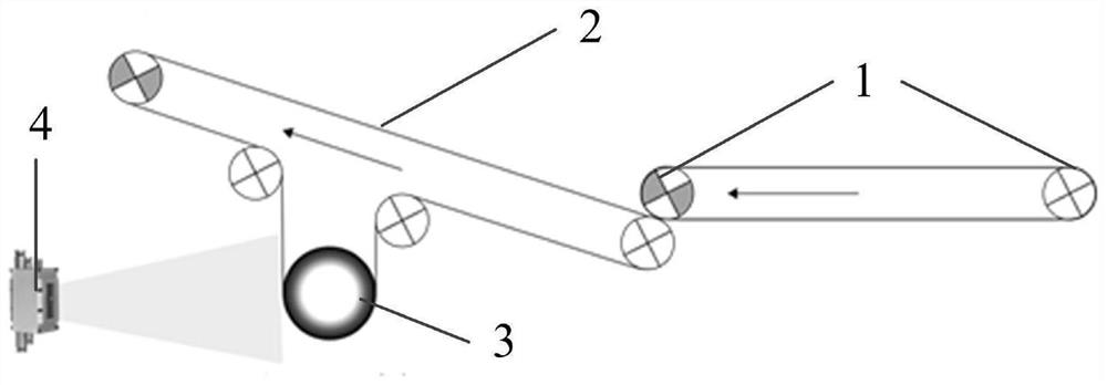
[0039] like figure 1 As shown, the belt tension monitoring system ...


PUM


Abstract

The invention provides a belt tension monitoring system. The belt tension monitoring system comprises a tensioning trolley, a three-dimensional camera and a controller, wherein the tensioning trolley is connected with a belt conveyor through a belt with tension to be monitored; the tensioning trolley moves along with the tension change of the belt; the three-dimensional camera is arranged on one side of the tensioning trolley and used for monitoring the position changes of the tensioning trolley and transmitting three-dimensional image data of the position changes to the controller; and the controller calculates a linear distance between the tensioning trolley and the three-dimensional camera according to the three-dimensional image data and judges whether the linear distance is within a normal threshold range or not, and if so, the belt is normal, or if not, the belt is abnormal, and the controller controls the belt conveyor to stop. According to the invention, a tensioning trolley monitoring device based on a three-dimensional video technology is provided, the position relation of the belt tensioning trolley is monitored in real time, and whether the belt tension is abnormal or not is judged in an auxiliary mode according to rigid connection attributes and preset safety belt tension displacement interval values, so real-time quantitative monitoring of the belt tension is achieved.

Description

technical field [0001] The invention relates to the monitoring field, in particular to a belt tension monitoring system. Background technique [0002] The existing belt tension monitoring device mainly relies on the limit devices at both ends of the belt running range to adjust the tightness of the belt. It will be adjusted, and the belt tension is in an unsafe state near the limit, so the existing belt tension monitoring device cannot monitor whether the belt tension is in a safe range in real time, so that the belt tension When the safety range is exceeded, there is no alarm or shutdown, so it is impossible to avoid material spillage or even more serious transportation accidents caused by excessive tension, slack or breakage of the belt. Contents of the invention [0003] The purpose of the present invention is to provide a belt tension monitoring system capable of monitoring the belt tension in real time. [0004] To achieve the above object, the present invention pro...

Claims


Application Information

Patent Timeline
Patent Type & Authority Applications(China)
IPC IPC(8): B65G43/02
CPCB65G43/02
Inventor 李铮戴卫东顾其洋李函阳费翔
Owner NINGXIA GUANGTIANXIA ELECTRONICS TECHNOLOGY CO LTD
Learn More