Bone cement filler suite

A technology of bone cement and filler, applied in the field of medical devices, to achieve the effects of reducing diffusion, improving injection efficiency, and increasing the mixing range

Inactive Publication Date: 2022-03-01
HENAN CANCER HOSPITAL
View PDF0 Cites 0 Cited by
  • Summary
  • Abstract
  • Description
  • Claims
  • Application Information

AI Technical Summary

Problems solved by technology

[0007] In order to make up for the deficiencies of the prior art, solve the problem of how to improve the bonding ability, firmness and mechanical properties of bone cement, and improve the therapeutic effect of bone cement on patients with osteoporotic vertebral compression fractures, the present invention proposes a bone cement filling device kit

Method used


Image

  • Bone cement filler suite
  • Bone cement filler suite
  • Bone cement filler suite

Examples


Embodiment 1

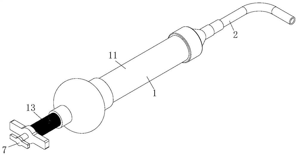
[0039] A bone cement filler kit such as Figure 1-3 As shown, it includes a sleeve set 1 and an extension tube set 2; the sleeve set 1 includes a mixer body 11, a bone cement mixer O-ring, an inner push rod 12 and a T-shaped outer push rod 13; the extension Tube set 2 is a long extension tube set or a short extension tube set; also includes:

[0040] Elastic push block 3, the elastic push block 3 is used to push the bone cement in the mixer barrel 11;

[0041] Groove 31, described groove 31 is provided on the elastic push block 3;

[0042] No. 1 channel 4, said No. 1 channel 4 is set in the elastic push block 3, inner push rod 12 and T-shaped outer push rod 13 connected in sequence;

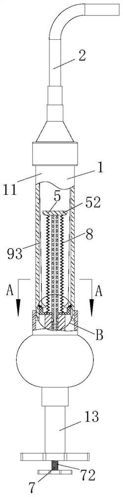
[0043] Stirring group 5, described stirring group 5 comprises stirring rod 51, stirring block 52, No. 1 magnetic block 53 and clamping module 6; One end of described stirring rod 51 is connected with stirring block 52 placed in groove 31, and the other end Connect with the No. 1 magnetic block...

Embodiment 2

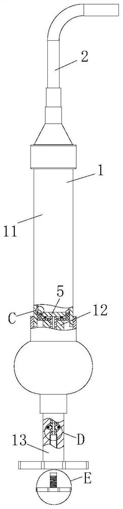
[0049] The difference from Embodiment 1 is that, as image 3 and Figure 7 As shown, the engaging module 6 includes a clamping block 61, an annular clamping groove 62 and a clamping groove 63; the inner wall of the No. 1 channel 4 is provided with a clamping groove 63; the outer ring of the stirring rod 51 There is an annular snap-in groove 62 on the top, and in the initial state, the snap-in slot 63 corresponds to the annular snap-in slot 62; Inside;

[0050] Through the mutual cooperation between the clamping block 61 and the annular clamping groove 62, the engagement and fixation of the stirring rod 51 can be realized, and the force of the pushing rod 72 can be pushed outward to realize the engagement between the clamping block 61 and the annular clamping groove 62. Detachment does not need to add an additional driving source, and at the same time, the operation is simple and stable;

[0051] The difference from the specific working process of Embodiment 1 is that when t...

Embodiment 3

[0053] The difference from the second embodiment is that, if image 3 as well as Figure 7-Figure 8 As shown, a group of balls 41 are arranged on the inner wall of the No. 1 channel 4 located at the bottom of the No. 1 magnetic block 53, and the inner diameter formed between the corresponding balls 41 on the inner wall of the No. 1 channel 4 is much larger than that of the No. 2 magnet. The width of piece 71; Described push rod 72 is made up of rod one 721 and rod two 722, and rod one 721 connects No. 2 magnetic block 71, and rod one 721 and rod two 722 are rotationally connected, and the outer ring of rod one 721 is opened There is a spiral groove 723 matching with the ball 41;

[0054] By setting the push rod 72 composed of rod one 721 and rod two 722, and on the rod one 721, a spiral groove 723 matching the ball 41 is provided, and the spiral groove 723 cooperates with the ball 41, thereby realizing the stirring rod 51 and the stirring The rotation of the block 52 increas...


PUM


Abstract

The invention belongs to the technical field of medical instruments, and particularly relates to a bone cement filler suite which comprises a sleeve set and an extension pipe set. The sleeve group comprises a stirrer barrel body, a bone paste stirrer O-shaped ring, an inner push rod and a T-shaped outer push rod; the extension pipe group is a long extension pipe group or a short extension pipe group; the device further comprises an elastic push block, a groove, a first channel, a stirring set and an external connection set. The stirring group is always placed in the sleeve group, so that the influence of the stirring group on injection of bone cement can be avoided, the generation of bubbles caused by mixing of air during stirring can be avoided, the bonding performance and the firmness of the bone cement are improved, meanwhile, diffusion of a bone cement monomer can be reduced, the odor of the bone cement monomer is reduced, and the service life of the bone cement is prolonged. In addition, complicated assembling and disassembling steps before bone cement injection are reduced, and the bone cement injection efficiency is improved.

Description

technical field [0001] The invention belongs to the technical field of medical instruments, in particular to a bone cement filler kit. Background technique [0002] Osteoporosis is a common disease in geriatric orthopedics, and osteoporotic vertebral compression fracture is one of the most common complications of osteoporosis; due to pain, spinal deformity and other reasons, patients with osteoporotic vertebral compression fracture Often the amount of activity decreases and the lung capacity decreases, which seriously affects the quality of life of patients; with the acceleration of the aging process of the Chinese population, the incidence of osteoporotic vertebral compression fractures increases year by year, and the incidence rate of women is higher than that of men; due to osteoporosis Most patients with osteoporotic vertebral compression fractures are elderly people with many comorbidities. In the past, conservative treatments such as bed rest, wearing braces, oral calc...

Claims


Application Information

Patent Timeline
Patent Type & Authority Applications(China)
IPC IPC(8): A61B17/88
CPCA61B17/8805A61B17/8833A61B2017/8838
Inventor 王鑫
Owner HENAN CANCER HOSPITAL
Why Eureka
Try Eureka