Friction welding method for target material assembly

A friction welding and target technology, applied in welding equipment, non-electric welding equipment, metal processing equipment and other directions, can solve the problems of low overall strength of the target material, good high temperature resistance, poor high temperature resistance, etc. Good high temperature performance and not easy to desolder

Active Publication Date: 2022-04-05
先导薄膜材料(安徽)有限公司
View PDF17 Cites 0 Cited by
  • Summary
  • Abstract
  • Description
  • Claims
  • Application Information

AI Technical Summary

Problems solved by technology
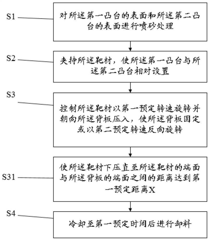
Among them, brazing uses low-melting-point metals such as indium as the intermediate layer to connect the target and the back plate. It is characterized by poor high temperature resistance and low bonding strength. Poor welding will lead to desoldering of the target during use; electron beam welding is used in Under the action of the high-energy electron beam, the target is melted to form a metallurgical bond, but its welding area is narrow, about ten millimeters, resulting in low overall strength of the target, and it is often used as a welding method for bowl-shaped aluminum targets; diffusion welding is in Under the protection of inert gas, under the action of high temperature for a long time, it is a large-area welding technology that realizes the metallurgical combination of the target and the back plate through interatomic diffusion. It has high bonding strength and high temperature resistance.
However, diffusion welding is time-consuming and expensive, so it is urgent to develop a cost-effective metallurgical bonding welding method

Method used


Image

  • Friction welding method for target material assembly
  • Friction welding method for target material assembly
  • Friction welding method for target material assembly

Examples


Embodiment Construction

[0024] The following will clearly and completely describe the technical solutions in the embodiments of the present application with reference to the accompanying drawings in the embodiments of the present application. Obviously, the described embodiments are only part of the embodiments of the present application, not all of them. Based on the embodiments in this application, all other embodiments obtained by persons of ordinary skill in the art without making creative efforts belong to the scope of protection of this application.

[0025] It should be understood that in the description of this application, the terms "center", "upper", "lower", "front", "rear", "left", "right", "vertical", "horizontal", The orientations or positional relationships indicated by "top", "bottom", "inner", "outer", etc. are based on the orientations or positional relationships shown in the drawings, and are only for the convenience of describing the application and simplifying the description, rat...


PUM

PropertyMeasurementUnit
heightaaaaaaaaaa
heightaaaaaaaaaa
thicknessaaaaaaaaaa

Abstract

The invention relates to the technical field of welding, and discloses a friction welding method of a target material assembly, according to the friction welding method, heat generated by friction between a target material rotating at a high speed and a back plate is used for locally melting a first boss and a second boss, and a compact solid-phase welding seam is formed under extrusion of a welding tool. According to the friction welding method, the welding bonding layer is formed through melting, the bonding strength is higher than that of brazing indium, the high-temperature resistance is better, and desoldering is not prone to occurring; compared with electron beam welding, the welding area of the first boss and the second boss is larger, namely, the metallurgical bonding area is larger, and the overall strength is higher; compared with diffusion welding, the friction welding method is shorter in consumed time, inert gas or other working conditions do not need to be adopted for protection, and the cost is low; and secondly, the friction welding method is small in friction force, low in equipment requirement, low in energy consumption and short in welding time consumption, and small-area contact friction is not prone to causing overall deformation of the target material or the back plate.

Description

technical field [0001] The invention relates to the field of welding technology, in particular to a friction welding method for a target assembly. Background technique [0002] In the semiconductor field, there are three main ways to weld the target and the back plate: brazing, electron beam welding, and diffusion welding. Among them, brazing uses low-melting-point metals such as indium as the intermediate layer to connect the target and the back plate. It is characterized by poor high temperature resistance and low bonding strength. Poor welding will lead to desoldering of the target during use; electron beam welding is used in Under the action of the high-energy electron beam, the target is melted to form a metallurgical bond, but its welding area is narrow, about ten millimeters, resulting in low overall strength of the target, and it is often used as a welding method for bowl-shaped aluminum targets; diffusion welding is in Under the protection of inert gas, under the a...

Claims


Application Information

Patent Timeline
Patent Type & Authority Applications(China)
IPC IPC(8): B23K20/12
CPCY02E30/10
Inventor 黄旭东黄宇彬童培云朱刘
Owner 先导薄膜材料(安徽)有限公司
Why Eureka
Try Eureka