Check patentability & draft patents in minutes with Patsnap Eureka AI!

Seat back machanism

A backrest and backrest technology, applied in transportation and packaging, special positions of vehicles, chairs, etc., can solve problems such as the weakening of the sliding plate and ratchet meshing state

Inactive Publication Date: 2004-05-05
ARACO CORP
View PDF1 Cites 0 Cited by
  • Summary
  • Abstract
  • Description
  • Claims
  • Application Information

AI Technical Summary

Problems solved by technology

For this reason, when there is a load on the backrest device in this state, the sliding plate has a slight rotational movement due to the looseness between the connecting parts and the sliding plate, and the meshing state of the sliding plate and the ratchet is weakened. state

Method used


Image

  • Seat back machanism
  • Seat back machanism
  • Seat back machanism

Examples


Embodiment Construction

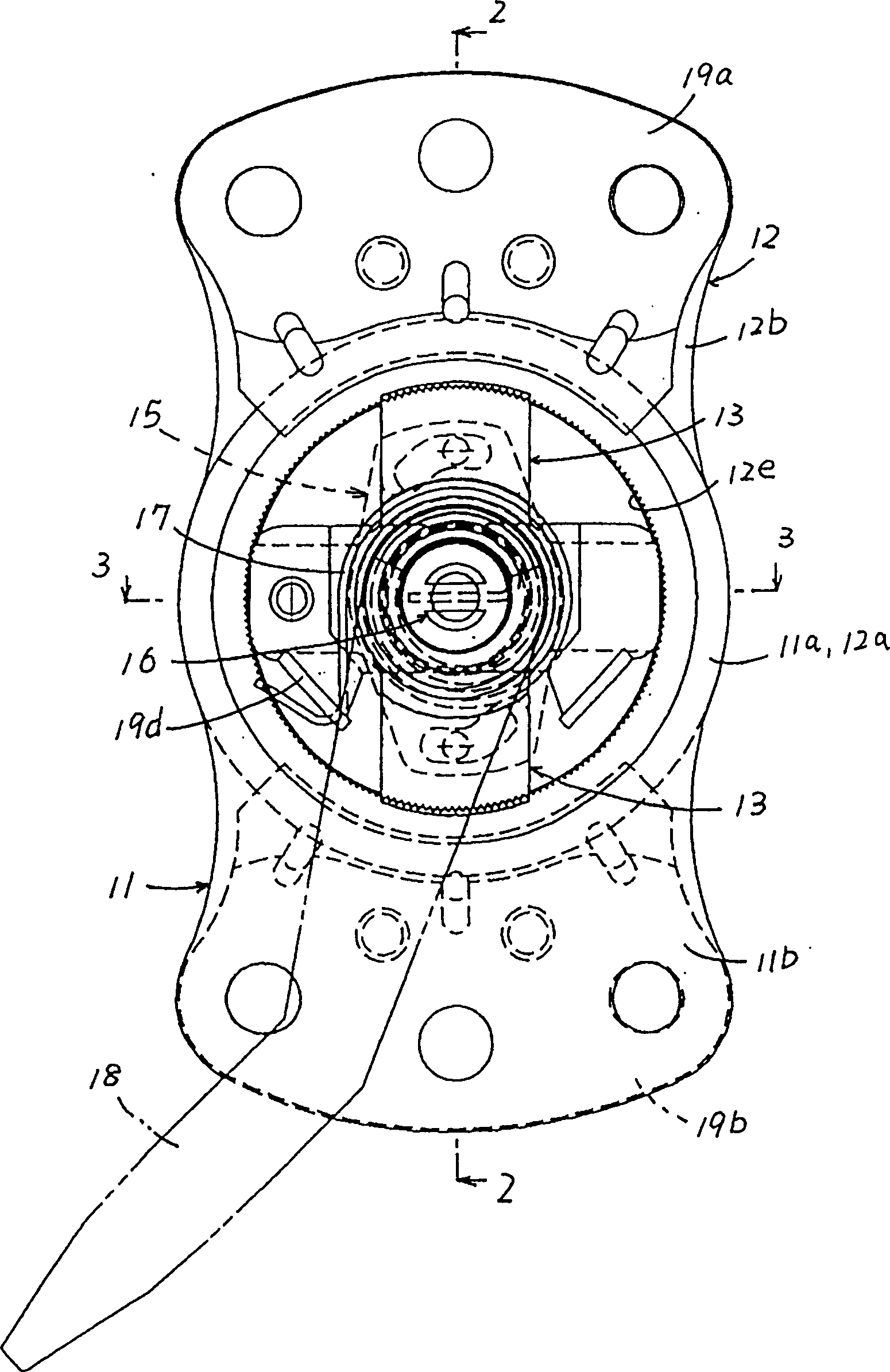
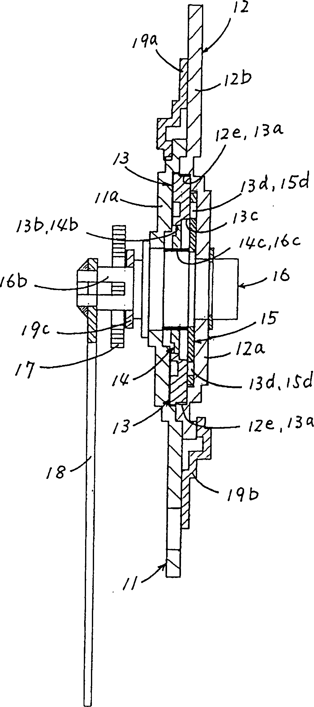
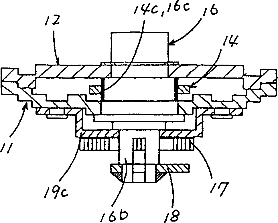
[0028] The present invention will be described below with reference to the accompanying drawings. Figure 1 to Figure 3 It shows an example of the backrest apparatus concerning this invention. The backrest device includes a first link arm 11 , a second link arm 12 , a pair of slide plates 13 , a receiving plate 14 , a motion transmission plate 15 , a hinge shaft 16 , a coil spring 17 , and an operating lever 18 .

[0029] The first link arm 11 and the second link arm 12 accommodate the two sliding plates 13 , the receiving plate 14 and the motion transmission plate 15 in a state of overlapping each other, and are rotatably supported on the hinge shaft 16 , The first link arm 11 is fixed to the rear side of the seat side of the chair (not shown), and the second link arm 12 is fixed to the back side of the chair (not shown).

[0030] In this way, the backrest device connects the back of the chair to the rear end of the seat of the chair. When the two connecting arms 11 and 12 a...


PUM


Abstract

An arc shape bore part on the back part of a slide pole is borne by an arc shape bearing part of a bearing plate to keep an engaging condition between the slide pole and a ratchet to regulate the rotation of the slide pole under load action to prevent lowering of engaging strength caused by the rotation of the slide pole to increase the engaging strength. It prevents lowering of the interlocking strength between a slide pole and a ratchet under a load action in a reclining device in which a slide pole assembled with a first connecting arm is slid to engage with a ratchet equipped on a second connecting arm to lock both arms.

Description

technical field [0001] The invention relates to a backrest device Background technique [0002] As a form of the backrest device, there is a backrest device comprising a pair of connecting arms respectively installed on the seat side of the chair and the back side of the chair, a hinge shaft supporting the two connecting arms and relatively rotatable around the support axis, a A sliding plate that is slidably mounted on one of the two connecting arms and can be engaged with a ratchet wheel arranged on the other connecting arm, allowing the sliding plate to slide and selectively form the engaging state of the sliding plate to the ratchet wheel and the non-engaging state of the ratchet wheel. In the meshing state, the relative rotation of the two connecting arms is restricted by the meshing state. [0003] In the backrest device of the above type, the engagement state is configured to restrict the relative rotation of the two link arms, so that the chair back is locked relati...

Claims


Application Information

Patent Timeline
IPC IPC(8): A47C1/025B60N2/235
CPCB60N2/2356B60N2/236
Inventor 浅野诚
Owner ARACO CORP
Features
  • R&D
  • Intellectual Property
  • Life Sciences
  • Materials
  • Tech Scout
  • Unparalleled Data Quality
  • Higher Quality Content
  • 60% Fewer Hallucinations
Learn More