

Microwave device including mesh component
A microwave device and mesh technology, which is applied in microwave heating, electric heating devices, electrical components, etc., can solve problems such as weak strength, low microwave cut-off rate, and difficulty in improving porosity
- Summary
- Abstract
- Description
- Claims
- Application Information
AI Technical Summary
Problems solved by technology
Method used
Image

Examples
Embodiment Construction
[0058] A microwave device including a mesh member according to a preferred embodiment of the present invention will be described below with reference to the accompanying drawings.
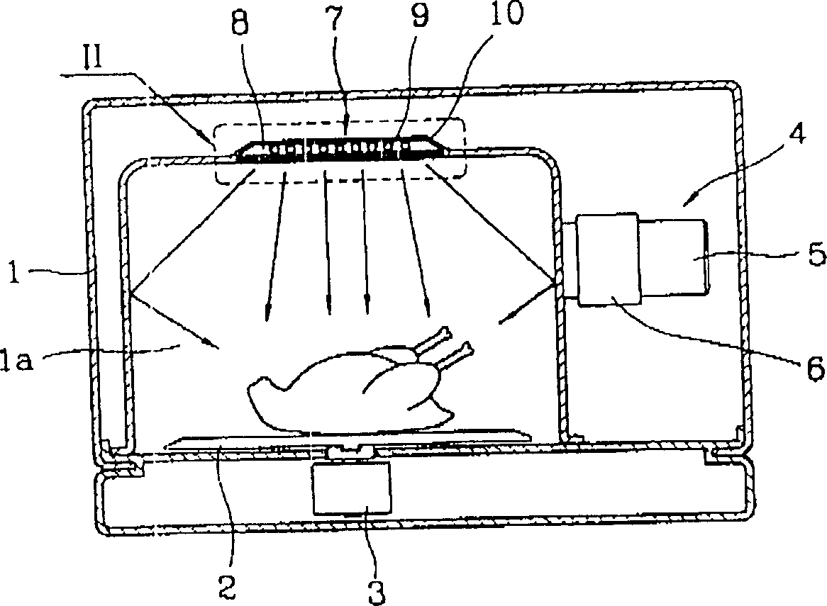
[0059] Figure 9 Shown is a front view of the internal structure of an electric oven including a mesh member according to the present invention.
[0060] As shown in the figure, wherein, the electric oven comprising the mesh part comprises: a case 1 having a cooking chamber 1a for cooking food; A drive motor 3 for rotating the turntable below the turntable; a high-frequency generating device 4 including a magnetron 5 and a waveguide 6 for generating electric pulses in the cooking chamber 1a, and the high-frequency generating device 4 is installed in the cooking chamber 1a and a heating or light irradiation device 7 independently installed on the cooking chamber 1a for providing heat radiation and light radiation to the cooking chamber 1a.
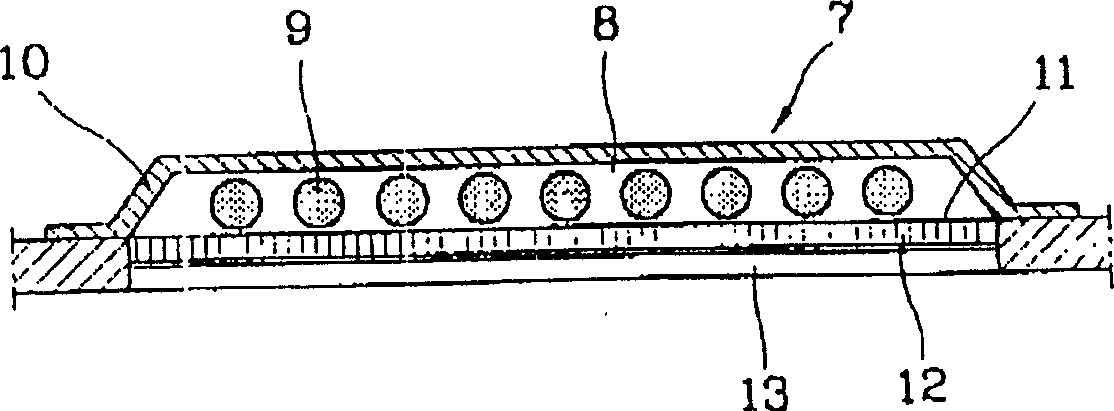
[0061] Here, in the heating or light irradiation device ...
PUM
 Abstract
Description
Claims
Application Information