Receiving circuit of laser range finder

A technology of laser rangefinder and receiving circuit, which is applied in the field of receiving circuit, can solve the problems of complex structure of laser receiving circuit, low cost performance, and limitation of popularization of laser tester, etc., and achieve the effect of simple structure, low energy consumption and long effective distance

Inactive Publication Date: 2015-04-29
成都昊地科技有限责任公司
View PDF0 Cites 1 Cited by
  • Summary
  • Abstract
  • Description
  • Claims
  • Application Information

AI Technical Summary

Problems solved by technology

Today's laser receiving circuit structure is too complicated, and the cost performance is too low, which greatly limits the popularization of laser testers

Method used


Image

  • Receiving circuit of laser range finder

Examples


Embodiment Construction

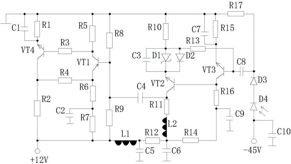
[0012] The present invention will be further described below in conjunction with accompanying drawing:

[0013] Such as figure 1 As shown, including the first power supply, the second power supply, the first capacitor C1, the second capacitor C2, the third capacitor C3, the fourth capacitor C4, the fifth capacitor C5, the sixth capacitor C6, the seventh capacitor C7, and the eighth capacitor C8, ninth capacitor C9, tenth capacitor C10, first resistor R1, second resistor R2, third resistor R3, fourth resistor R4, fifth resistor R5, sixth resistor R6, seventh resistor R7, eighth resistor R8, ninth resistor R9, tenth resistor R10, eleventh resistor R11, twelfth resistor R12, thirteenth resistor R13, fourteenth resistor R14, fifteenth resistor R15, sixteenth resistor R16, tenth Seven resistors R17, first transistor VT1, second transistor VT2, third transistor VT3, fourth transistor VT4, first diode D1, second diode D2, third diode Tube D3, fourth diode D4, first inductance L1 an...


PUM


Abstract

The invention discloses a receiving circuit of a laser range finder. The receiving circuit comprises a first power supply, a second power supply, first to tenth capacitors, first to seventeenth resistors, first to fourth triodes, first to fourth diodes, a first inductor and a second inductor. The receiving circuit is simple in structure, low in cost and high in amplification factor which is about 12,000 times, the bandwidth ranges from 0.5 MHz to 14 MHz, the output impedance is reduced, the transmission coefficient for low load impedance is increased, the directivity is high, energy consumption is low, and the effective range is wider.

Description

technical field [0001] The invention relates to a receiving circuit, in particular to a receiving circuit of a laser range finder. Background technique [0002] A laser range finder is a distance measuring instrument that uses laser pulses or continuous wave laser beams to measure the distance of a target. A laser range finder generally consists of three parts: a laser transmitter, a laser receiver and a power supply. The laser receiver is composed of receiving optical system, photodetector and amplifier, receiving circuit and counting display. The function of the device is to receive the laser pulse echo diffusely reflected from the target and calculate and display the target distance. Today's laser receiving circuit structure is too complicated, and the cost performance is too low, which greatly limits the popularization of laser testers. Contents of the invention [0003] The object of the present invention is to provide a simple and effective receiving circuit of a l...

Claims


Application Information

Patent Timeline
Patent Type & Authority Applications(China)
IPC IPC(8): G01S7/484
CPCG01S7/4861G01S7/4913G01S17/08
Inventor 靖新宇
Owner 成都昊地科技有限责任公司
Why Eureka
Try Eureka