Motor-assisted bicycle

An electric assist, bicycle technology, applied in electric vehicles, control drive, power management, etc., can solve the problems of unable to follow sudden pedal force changes, control lag, etc.

Inactive Publication Date: 2005-08-03
HONDA MOTOR CO LTD
View PDF0 Cites 0 Cited by
  • Summary
  • Abstract
  • Description
  • Claims
  • Application Information

AI Technical Summary

Problems solved by technology

That is, the assist force output at the present time is the assist force corresponding to the past pedaling force, so there is a problem that control lag occurs and it cannot follow a sudden change in the pedaling force.

Method used


Image

  • Motor-assisted bicycle
  • Motor-assisted bicycle
  • Motor-assisted bicycle

Examples


Embodiment Construction

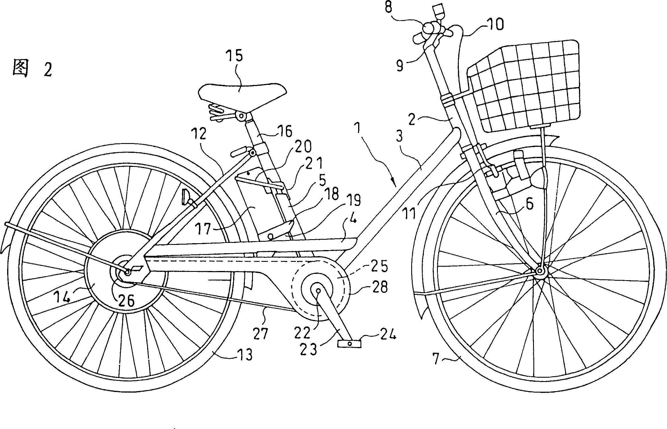
[0023] Next, an embodiment of the present invention will be described with reference to the drawings. Fig. 2 is a side view of a power-assisted bicycle provided with a control device according to an embodiment of the present invention. The body frame 1 of the electric assisted bicycle has a top tube 2 positioned at the front of the car body, a slant beam 3 extending rearward and downward from the top tube 2, a rear fork 4 connected to the slant beam 3 and extending rearward, and the uppermost end of the slant beam 3. The lower end stands to the pillar 5 above.

[0024] A front fork 6 is rotatably supported on the top tube 2 . The lower end of front fork 6 supports front wheel 7 with bearing, and steering handle 8 is installed at the upper end of front fork 6. A brake lever 9 is arranged on the steering handle 8 , and a cable 10 drawn from the brake lever 9 is connected to a front wheel brake 11 fixed on the front fork 6 . Similarly, although the brake lever that the rear wh...


PUM


Abstract

The invention determines an assist force, which is more suitable for a running condition by improving delay of an assist control and failures in determining the assist force in proportion to a pedaling force alone. A filter part 51 compares a detected pedaling force with a predetermined reference pedaling force according to a corresponding crank angle, and estimates a peak value of the pedaling force. Furthermore, it estimates an average value based on the peak value. A steady pedaling force reference value corresponds to flat land running resistance responding to a speed. A steady assist computing part 53 calculates a steady assist force from the average pedaling force and the reference steady pedaling force by PID control. The steady assist force is calculated in a manner to be increased when the average pedaling force is increased, and to be decreased when the reference steady pedaling force is increased. A proportional assist calculating part 50 calculates a proportional assist force, which is proportional to the detected pedaling force. The proportional assist force and the steady assist force are added so as to find an assist force.

Description

technical field [0001] The present invention relates to a power-assisted bicycle, and particularly relates to a power-assisted bicycle capable of giving an appropriate power-assist force (assist force) in consideration of a pedaling force that changes periodically according to a crank angle of rotation. Background technique [0002] Electrically assisted bicycles are known that have a human-powered drive system for transmitting the force applied by human power to the pedals, that is, the pedaling force, to the rear wheel, and a motor drive system that can add auxiliary power to the human-powered drive system in response to the pedaling force. In this electrically assisted bicycle, when a pedaling force is applied using a crank pedal, the pedaling force changes periodically according to the rotation angle of the crankshaft, that is, the crank angle. Thus, the current supplied to the motor that applies the auxiliary power will also vary with pedaling force. In this way, if th...

Claims


Application Information

Patent Timeline
Patent Type & Authority Patents(China)
IPC IPC(8): B60L15/20B62M6/65
CPCY02T10/7258B62M6/45B62M6/65Y02T10/72
Inventor 本田聪
Owner HONDA MOTOR CO LTD
Why Eureka
Try Eureka