
Powered steering system

A technology of power steering and steering valve, applied in power steering mechanism, automatic steering control components, steering mechanism, etc., can solve problems such as energy loss

Inactive Publication Date: 2006-09-06
KYB CORP
View PDF1 Cites 0 Cited by
  • Summary
  • Abstract
  • Description
  • Claims
  • Application Information

AI Technical Summary

Problems solved by technology

[0039] Setting the standby flow with respect to low vehicle speeds leads to the problem of energy loss due to providing more than required standby flow at high speeds

Method used


Image

  • Powered steering system
  • Powered steering system
  • Powered steering system

Examples


Embodiment Construction

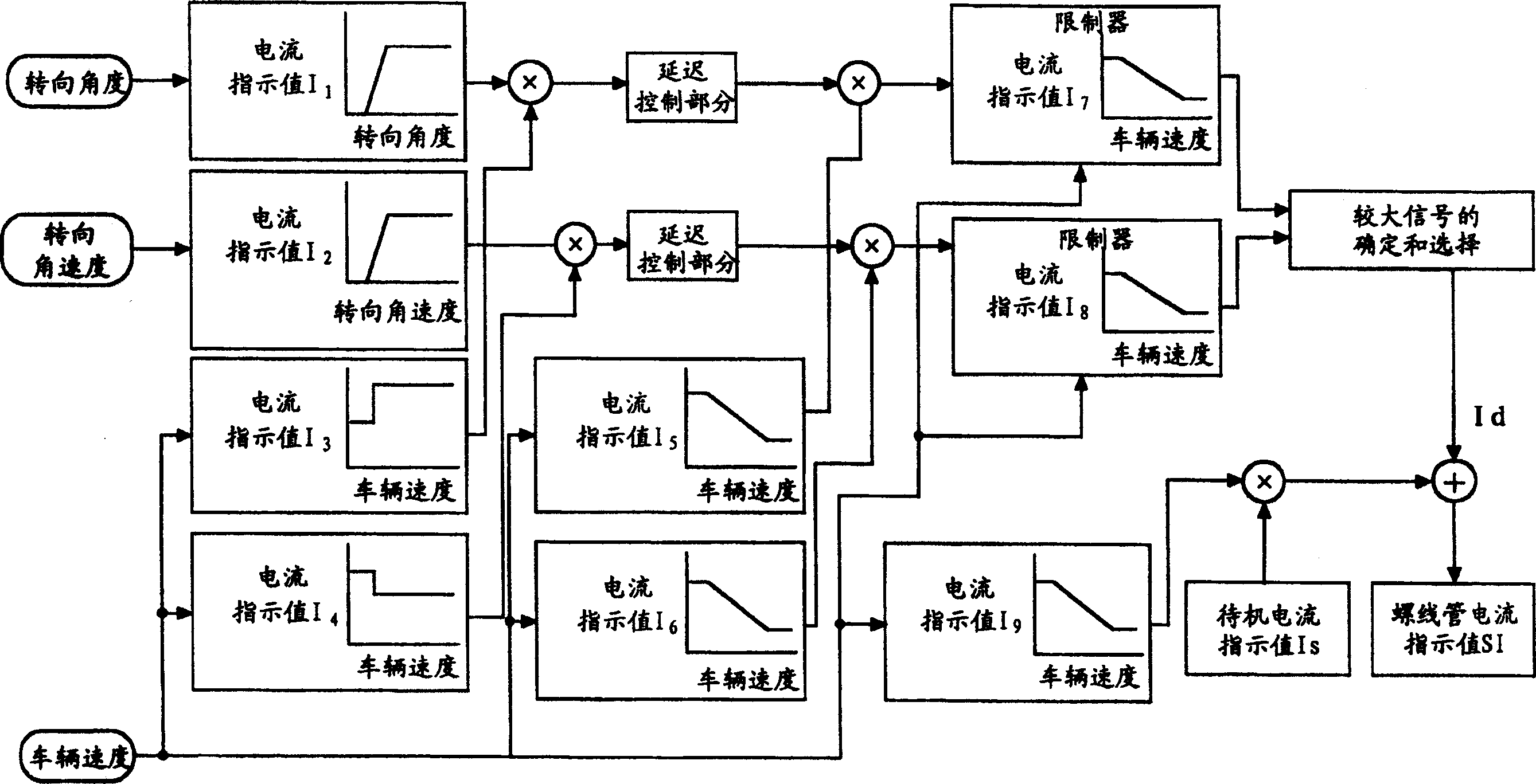
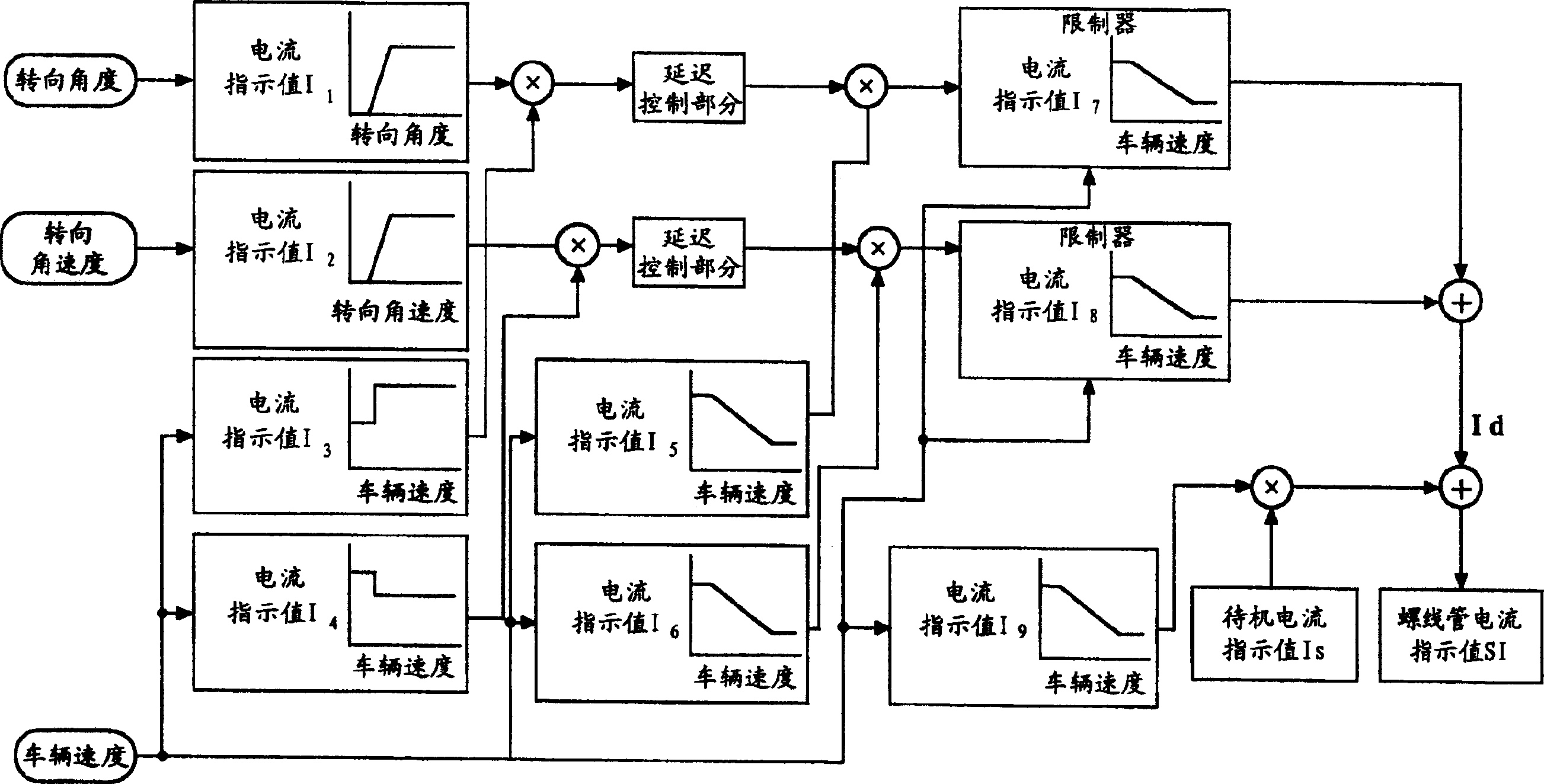
[0055] figure 1 The control system of the controller C of the first embodiment is illustrated. In the case of the first embodiment, except for the controller C, the power steering system has the same configuration as the prior art example, including Figure 7 The flow control valve V, the power cylinder 8, the steering valve 9, etc. illustrated in , and the description of the control system of the controller C will be given below.

[0056] Such as figure 1 As illustrated in , the controller C determines a current indication value I1 based on the steering angle detected by the steering angle sensor 14 and a current indication value I2 based on the steering angular velocity calculated by differentiating the steering angle. Note that a steering angular velocity sensor may be additionally provided to determine the current indication value I2 based on the steering angular velocity detected by this steering angular velocity sensor.

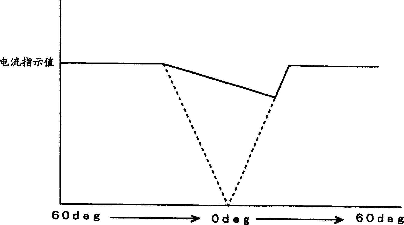
[0057] The relationship between the steering ...


PUM


Abstract

A power steering system capable of preventing an unnecessary standby flow produced in high speed travel. A controller C determines a basic current instruction value Id based on a current instruction value I1 in accordance with a steering angle detected by a steering angle sensor 14, a current instruction value I2 in accordance with a steering angular velocity and current instruction values I5, I6 in accordance with a vehicle speed, and adds a standby current instruction value Is to the basic current instruction value Id, and outputs the resultant value of the addition as a solenoid current instruction value SI, and changes the standby current instruction value Is on the basis of the vehicle speed.

Description

technical field [0001] The present invention relates to a power steering system including a flow control valve for preventing energy loss. Background technique [0002] An example of a power steering system including a flow control valve for preventing energy loss is disclosed in published Japanese Patent Application No. 2001-260917 filed by the current applicant. [0003] Such as Figure 7 As shown in , the flow control valve V of the power steering system of the prior art example includes a spool 1 adjoining the servo chamber 2 at one end and the servo chamber 3 at the other end. [0004] The servo chamber 2 is in constant communication with the pump P through the pump hole 4 . The servo chamber 2 communicates with the inflow port of the steering valve 9 provided for controlling the power cylinder 8 through the flow channel 6, the variable orifice a and the flow channel 7 [0005] The servo chamber 3 includes the spring 5 and also communicates with the inlet of the steer...

Claims


Application Information

Patent Timeline
Patent Type & Authority Patents(China)
IPC IPC(8): B62D5/065B62D6/00B62D5/07B62D6/02B62D101/00B62D113/00B62D119/00
CPCB62D6/02B62D5/065B62D5/06
Inventor 清水升有田恒文岛直人高井正史
Owner KYB CORP
Learn More