Supercharge Your Innovation With Domain-Expert AI Agents!

Drying device

A technology of drying device and air supply device, which is applied in the direction of drying gas arrangement, drying solid material, progressive dryer, etc., and can solve the problems of large operating costs and so on

Inactive Publication Date: 2006-10-04
ALPS ALPINE CO LTD
View PDF0 Cites 0 Cited by
  • Summary
  • Abstract
  • Description
  • Claims
  • Application Information

AI Technical Summary

Problems solved by technology

For this reason, an exhaust device is installed around the air knife to forcibly remove the mist to prevent it from adhering to the substrate again, so that more operating costs are required for forced exhaust.

Method used


Image

  • Drying device
  • Drying device
  • Drying device

Examples


Embodiment

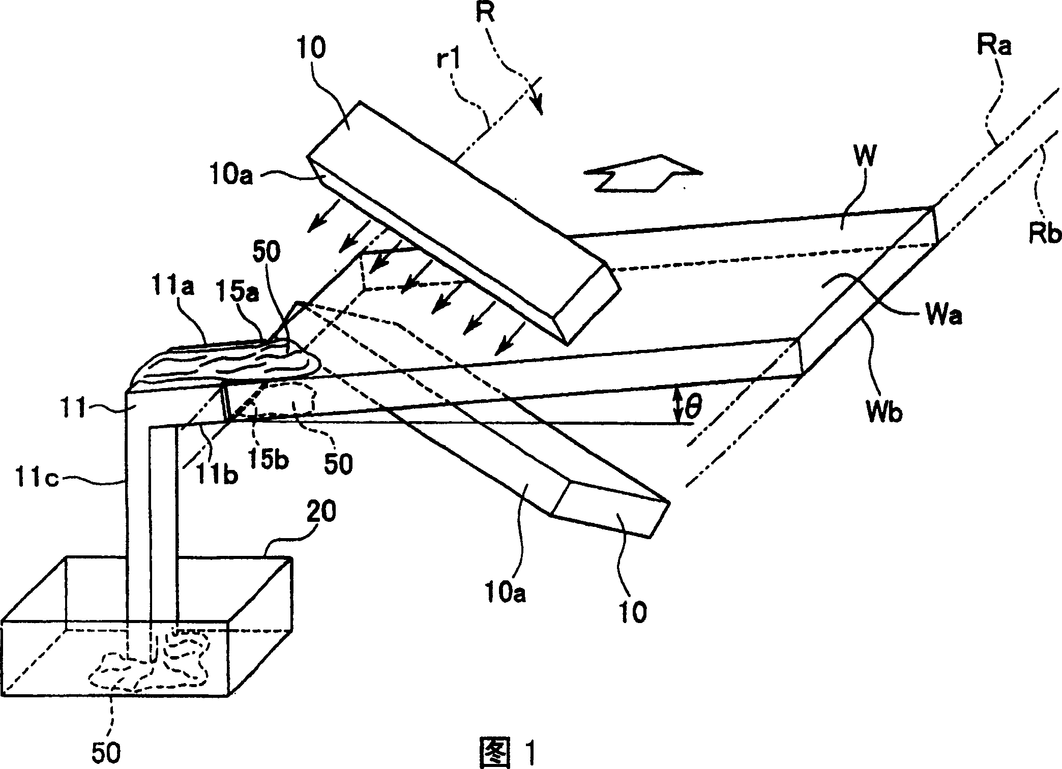
[0093] In order to actually verify the effect of the present invention, the present inventor actually manufactured a drying device constituted by the present invention.

[0094] The drying apparatus of this embodiment is based on the above-mentioned embodiment 1, and the inclination angle of the substrate during transportation (that is, the inclination angle of the transportation path) is 2°, and the drying process is performed. cm) In comparison, only about 1 / 10 of the air blowing force can make the processing liquid flow from the substrate to the plate member side.

[0095] According to the present invention described in detail above, since the treatment liquid is recovered in the form of a liquid without being scattered into the air, the blowing force of the blowing device can be reduced, and the running cost for blowing can be reduced. Furthermore, since the processing liquid is recovered in a liquid state, it is not necessary to provide an additional exhaust device to rec...


PUM


Abstract

Provided is a drier in which compressed air is blown to a substrate carried almost in the horizontal direction by a carrier roll to remove a treating liquid so as to remove the treating liquid without blowing off the liquid. The drier is constituted by being equipped with a carrying means having a carrying passage R to carry a substrate W having liquid films or liquid droplets of the treating liquid 50 on the surfaces Wa, Wb in one direction, a blowing means 10 to blow drying air onto the surfaces Wa, Wb of the substrate W to move the liquid 50 to the upstream side of the carrying direction, and a liquid receiving means 11 which is disposed in contact or near the passage side r1 of the carrying passage R in the upstream side than the blowing means 10 and which receives the liquid 50 on the substrate surfaces Wa, Wb.

Description

technical field [0001] The present invention relates to a drying device for removing a treatment liquid by spraying compressed air onto a substrate conveyed substantially horizontally by conveying rollers. Background technique [0002] Generally, in the manufacturing process of substrates such as liquid crystal displays, it is necessary to dry the wet substrates in the drying tank after cleaning the substrates in the cleaning treatment tank by conveying rollers. Especially in recent years, in order to improve production efficiency, fast and powerful drying processing capabilities are required. Therefore, conventionally, an air-knife drying method in which treatment liquid such as water droplets adhering to the substrate is removed by air blowing has been employed. [0003] The so-called air knife drying method is to arrange a pair of air knives with long openings at the position sandwiched in the vertical direction by placing the substrate on the lower side supported by the...

Claims


Application Information

Patent Timeline
Patent Type & Authority Patents(China)
IPC IPC(8): H01L21/304F26B21/00F26B15/00G02F1/133G02F1/13B08B5/02F26B5/00
Inventor 渡部弘也三森健一伊藤卓雄
Owner ALPS ALPINE CO LTD
Features
  • R&D
  • Intellectual Property
  • Life Sciences
  • Materials
  • Tech Scout
  • Unparalleled Data Quality
  • Higher Quality Content
  • 60% Fewer Hallucinations
Learn More