Image forming apparatus

A technology of an imaging device and an optical detection mechanism, which is applied to instruments, equipment for electrical recording technology using charge patterns, optics, etc., can solve problems such as poor detection accuracy, inability to maintain high-quality images, and decreased density.

Inactive Publication Date: 2007-08-08
CANON KK
View PDF5 Cites 0 Cited by
  • Summary
  • Abstract
  • Description
  • Claims
  • Application Information

AI Technical Summary

Problems solved by technology

[0017] Therefore, in the case of measuring the optical intensity of the reflected light from the surface of the belt, that is, performing optical detection and controlling imaging conditions such as image density control based on the result, if the amount of reflected light from the belt is small, the detection accuracy will be poor. There is a problem that high-quality images cannot be maintained, such as density drops

Method used


Image

  • Image forming apparatus
  • Image forming apparatus
  • Image forming apparatus

Examples


Embodiment Construction

[0033] Next, an imaging device as an embodiment of the present invention will be described with reference to the drawings.

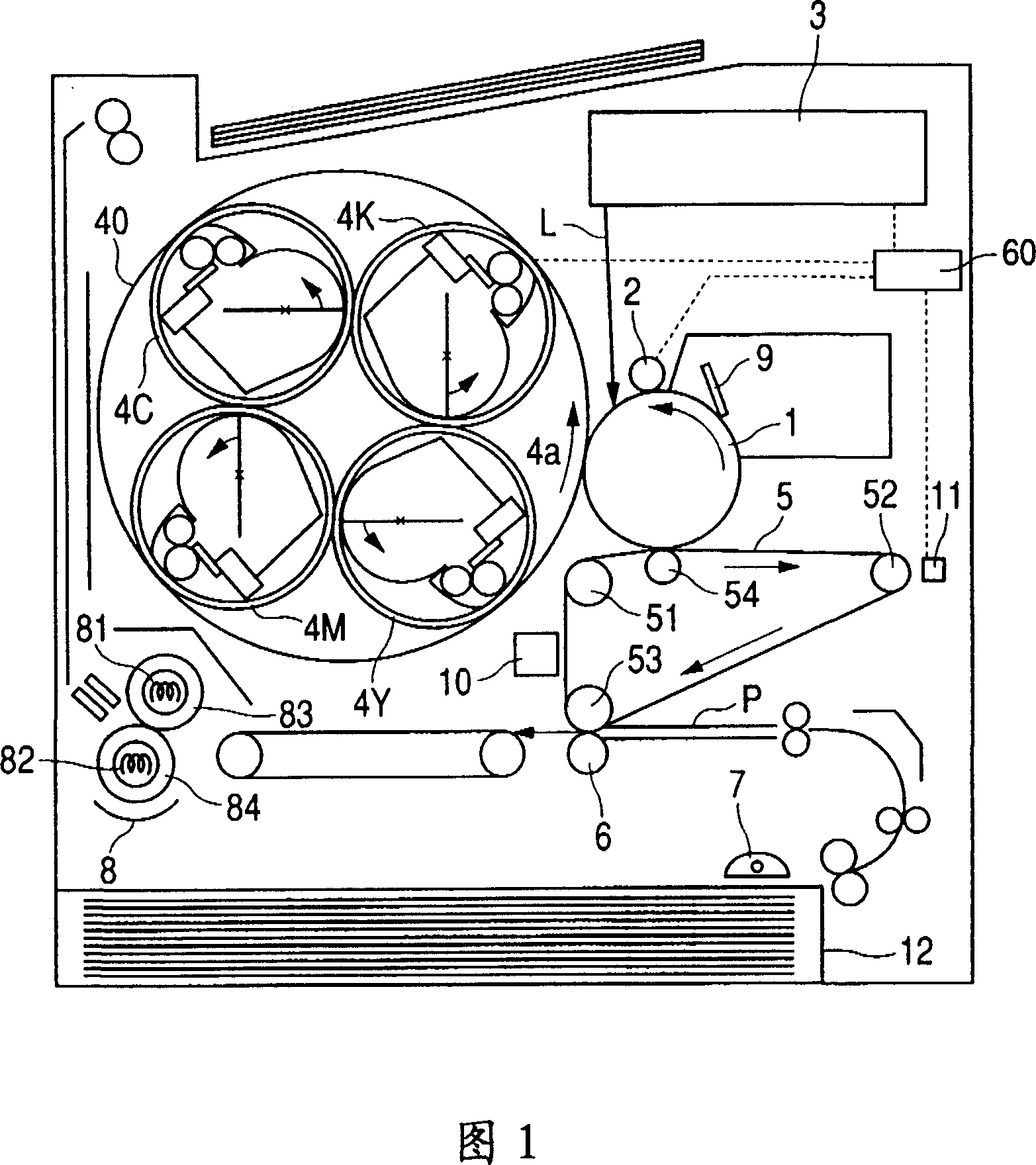
[0034] Here, description will be made using a schematic cross-sectional view of FIG. 1 showing a color image forming apparatus using electrophotographic processing as a basis of the present invention.

[0035] The color imaging device of Fig. 1 is a laser printer that adopts electrophotographic processing, and is composed of a first image carrier (photosensitive drum), a second image carrier (belt-shaped intermediate transfer body) and a plurality of developing units (with yellow, A color laser printer composed of developer cartridges for red, cyan, and black developers).

[0036] Next, the structure and operation form of each part of the color imaging device of this embodiment will be described in detail according to the imaging process.

[0037] As a first image bearing body, a rotating drum-type electrophotographic photoreceptor 1 (hereinafter referr...


PUM

PropertyMeasurementUnit
thicknessaaaaaaaaaa
sizeaaaaaaaaaa
widthaaaaaaaaaa

Abstract

An image forming apparatus an image bearing member adapted to bear a toner image and having a first glossiness in a first direction and a second glossiness lower than said first glossiness, and an optical detection unit including a light-emitting unit and a light-receiving unit, wherein a light emitted by the light-emitting unit is reflected by the image bearing member and is received by the light-receiving means and an optical direction from the light-emitting means to the light-receiving means is substantially same as the first direction of the image bearing member.

Description

technical field [0001] The present invention relates to image forming devices such as copiers and laser printers, and particularly relates to an image forming device that detects light from the surface of an image carrier. Background technique [0002] In recent years, various methods have been proposed and manufactured as image forming devices using electrophotographic image forming processing. FIG. 10 is a background art of the present invention, and is a schematic cross-sectional view of a color imaging device. [0003] In the photoreceptor unit including the first image carrier, a unit of the electrification member 2 and the cleaning member 9 is integrally arranged around the periphery of the drum-shaped photoreceptor 1 as the first image carrier. [0004] The exposure device 3 installed above the photoreceptor unit forms an electrostatic latent image based on image data on the surface of the photoreceptor 1 that has been electrified at a predetermined potential by the ...

Claims


Application Information

Patent Timeline
Patent Type & Authority Patents(China)
IPC IPC(8): G03G15/00G03G15/16G01N21/47
CPCG03G2215/0167G03G15/5058G03G2215/0103
Inventor 涩谷卓史小林达也紫村大斋藤圣史
Owner CANON KK
Why Eureka
Try Eureka