Accessory and recess indentification system for cirucit breakers

A technology for circuit breakers and accessories, which is applied in the field of identification systems for circuit breakers and accessories, and can solve problems such as spending a lot of non-productive time

Inactive Publication Date: 2002-08-28
ABB (SCHWEIZ) AG
View PDF0 Cites 5 Cited by
  • Summary
  • Abstract
  • Description
  • Claims
  • Application Information

AI Technical Summary

Problems solved by technology

In either case, a lot of

Method used


Image

  • Accessory and recess indentification system for cirucit breakers
  • Accessory and recess indentification system for cirucit breakers
  • Accessory and recess indentification system for cirucit breakers

Examples


Embodiment Construction

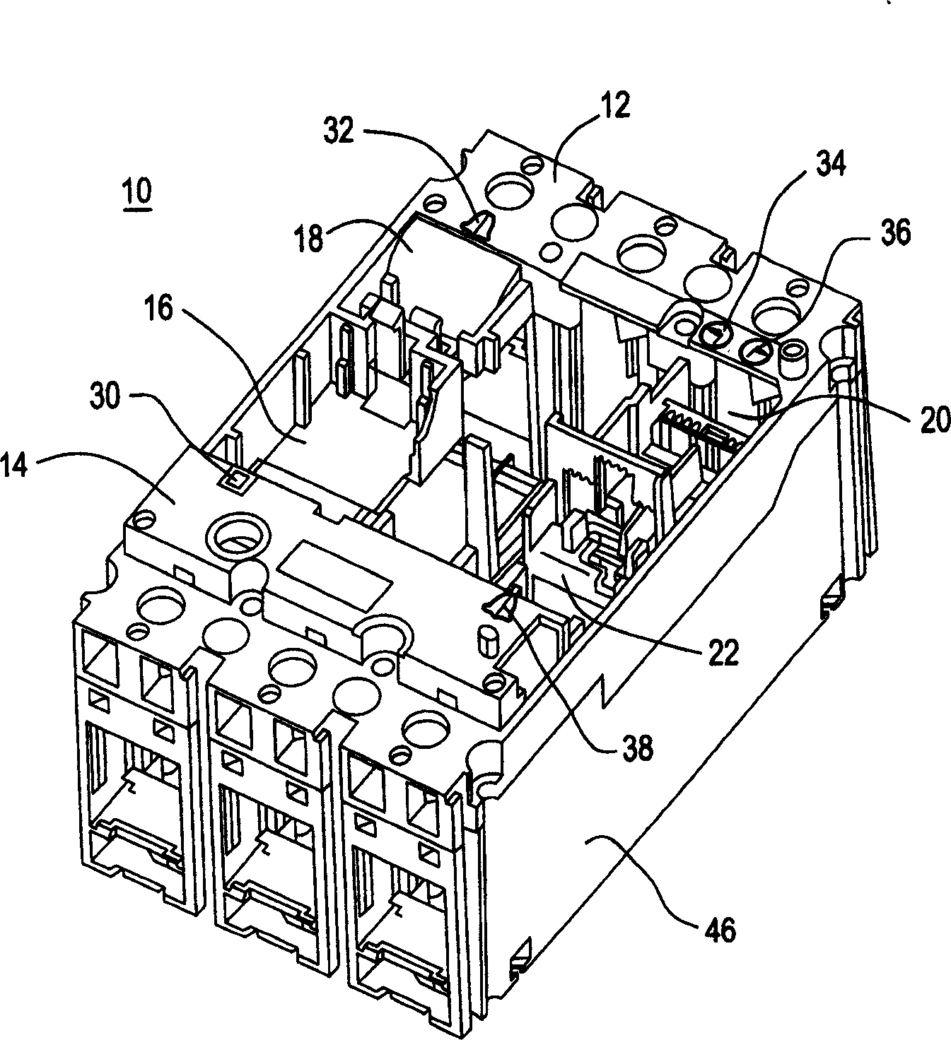
[0012] Such as figure 1 As shown, the circuit breaker 10 includes a molded frame 12 having an upper surface 14 and a plurality of recesses (both indicated by reference numeral 24 ) recessed from the upper surface 14 and a base portion 46. The molded frame 12 most Preferably made of plastic or other suitable insulating material. Each recess 24 is adapted to receive a particular model of circuit breaker accessory. Recess 16 may accommodate an undervoltage release mechanism ("UVR") or a shunt trip device ("SHT" or "ST"). The UVR is adapted to trip the breaker when the voltage drops by more than 35%, and should not trip when the voltage drops by more than 85% or more. The UVR has a maximum reaction time of 250 milliseconds. If there is a fault in the line, the SHT trips the circuit breaker with a reaction time of 15 milliseconds from pulse to trip. Recess 18 accommodates a warning mechanism ("BAM") and recess 22 accommodates a warning trip device ("BAT"). The BAM trips due to...


PUM


Abstract

The present invention discloses an identification system for identifying the correct position of various circuit breaker accessories (120, 130) within a recess (24) of a circuit breaker molding frame (12). The system includes groove symbols (26) adjacent grooves (24) in the frame (12) that match fitting symbols (52) located on front visible surfaces (122, 132) of fittings (120, 130). The system may also include a name tag (90) on the accessory (120, 130) for indicating a name (98) of the accessory. The invention also discloses a circuit breaker (10) using the identification system of the invention.

Description

Background of the invention [0001] The present invention relates to a circuit breaker and accessories, and more particularly to an identification system for circuit breakers and accessories. [0002] Although there are some standards for the basic functions of circuit breakers and their accessories, the appearance and internal functions of circuit breakers and various accessories can be marked with various classifications, and are given by different manufacturers and manufacturers. Many of the fittings are nearly identical in appearance except for the prongs on the back of the fittings, which act as latches for proper mating with fittings in recesses that share the same prongs. [0003] While an experienced professional electrician should eventually be able to distinguish these fittings and where they fit within the breaker frame, initial confusion can result in damage to the equipment. For less experienced professional electricians, this confusion may prevent them from prope...

Claims


Application Information

Patent Timeline
IPC IPC(8): H01H71/02H01H71/06
CPCH01H71/0228H01H71/06H01H2300/042
Inventor R·L·海恩M·H·托马斯K·格吕恩沃尔德特
Owner ABB (SCHWEIZ) AG
Why Eureka
Try Eureka