

Base station apparatus, communication terminal apparatus and communication method
A technology of communication terminals and base stations, which is applied in communication between multiple stations, wireless communication, multiplexing communication, etc., and can solve problems such as path misdetection, deterioration of reception quality, and deterioration of line estimation accuracy in data parts, etc.
- Summary
- Abstract
- Description
- Claims
- Application Information
AI Technical Summary
Problems solved by technology
Method used
Image

Examples
Embodiment 1
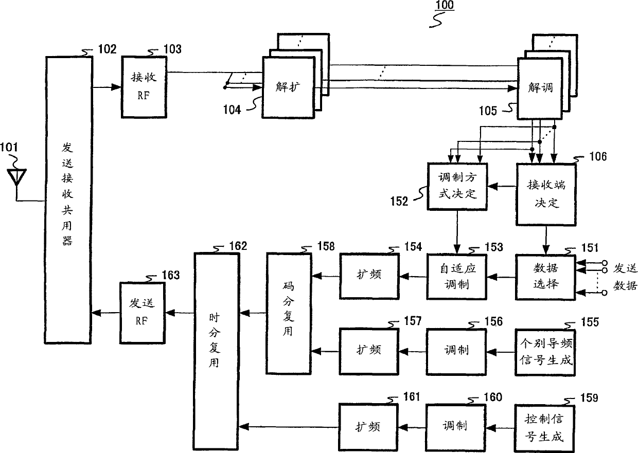
[0031] FIG. 4 is a block diagram showing the structure of base station apparatus 100 according to Embodiment 1 of the present invention.
[0032] In FIG. 4 , a base station apparatus 100 includes an antenna 101 , a duplexer 102 , a reception RF unit 103 , a despreading unit 104 , a demodulation unit 105 , and a receiving end determination unit 106 . The base station apparatus 100 further includes a data selection unit 151, a modulation scheme determination unit 152, an adaptive modulation unit 153, a spectrum spreading unit 154, an individual pilot signal generation unit 155, a modulation unit 156, a spectrum spreading unit 157, and a code division multiplexing unit 158 , a control signal generation unit 159 , a modulation unit 160 , a spectrum spreading unit 161 , a time division multiplexing unit 162 , and a transmission RF unit 163 .
[0033] The duplexer 102 outputs the signal received by the antenna 101 to the reception RF unit 103 . Also, the duplexer 102 wirelessly tra...
Embodiment 2
[0081] In Embodiment 2, a case where an adaptive array antenna (hereinafter referred to as "AAA") is applied to HDR will be described.
[0082] Fig. 7 is a block diagram showing the structure of a base station apparatus 300 according to Embodiment 2 of the present invention. In the base station apparatus 300 shown in FIG. 7, the same components as those of the base station apparatus 100 shown in FIG. 4 are given the same reference numerals as in FIG. 4, and description thereof will be omitted.
[0083] The base station apparatus 300 shown in FIG. 7 adopts the following configuration: Compared with the base station apparatus 100 shown in FIG. Section 351.
[0084]The duplexer 102 outputs each signal received by the antennas 301 to 303 to the reception RF unit 103 . Also, the duplexer 102 transmits each signal output from the transmission RF unit 163 through the antennas 301 to 303 .
[0085] The reception RF unit 103 converts each radio frequency reception signal output from...
Embodiment 3
[0097] Here, using one of the codes originally used for data transmission to transmit dedicated pilot signals results in lower transmission efficiency. In the case of using high-rate multi-value modulation methods such as 16QAM or 64QAM, it is easily affected by fading fluctuations, so it is necessary to use individual pilot signals to compensate the phase deviation of the data part, but when using low-rate modulation methods such as BPSK or QPSK In this case, the phase deviation of the data part can be sufficiently compensated even by using the common pilot signal.
[0098] In Embodiment 3, a case where transmission control of dedicated pilot signals is performed according to modulation schemes will be described.
[0099] Fig. 8 is a block diagram showing the structure of a base station apparatus 400 according to Embodiment 3 of the present invention. In base station apparatus 400 shown in FIG. 8 , the same components as those in base station apparatus 100 in FIG. 4 are assi...
PUM
 Abstract
Description
Claims
Application Information