
Movable installation device and installation method of microseismic sensor

A microseismic sensor and installation device technology, which is applied in the direction of measuring devices, seismic signal receivers, instruments, etc., can solve the problems of discounted signal reception performance of sensors, poor coupling quality between rock mass and probe, and influence on grouting effect, etc., to achieve Avoid poor grouting quality, good sealing effect, and prevent the effect of spraying grouting

Active Publication Date: 2021-10-26
CENT SOUTH UNIV
View PDF10 Cites 0 Cited by
  • Summary
  • Abstract
  • Description
  • Claims
  • Application Information

AI Technical Summary

Problems solved by technology

Due to the unevenness of the roadway wall, the drill hole opening is usually also irregular in shape, and the size of the wooden plug or rubber plug cannot completely match the drill hole, as the inside of the drill hole The increase of cement mortar will generate more and more pressure, which will easily lead to grouting and grout leakage during the grouting process. The coupling quality between the rock mass and the probe is poor, which seriously affects the grouting effect and makes the sensor receive Significantly compromised signal performance

Method used


Image

  • Movable installation device and installation method of microseismic sensor
  • Movable installation device and installation method of microseismic sensor
  • Movable installation device and installation method of microseismic sensor

Examples


Embodiment Construction

[0048] The following is a detailed description of the embodiments of the present invention. This embodiment is carried out based on the technical solution of the present invention, and provides detailed implementation methods and specific operation processes to further explain the technical solution of the present invention.

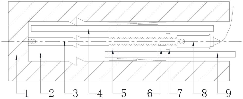
[0049] The movable mounting device of the microseismic sensor 8 provided in this embodiment, such as figure 1 As shown, it includes a grouting installation assembly and a grouting assembly, the grouting installation assembly includes an exhaust pipe 4, a grouting pipe 9 and several probes 3, and the grouting assembly includes a grouting plug near the bottom of the hole 5 , The part 6 near the orifice of the slurry plug and the compression nut 7.

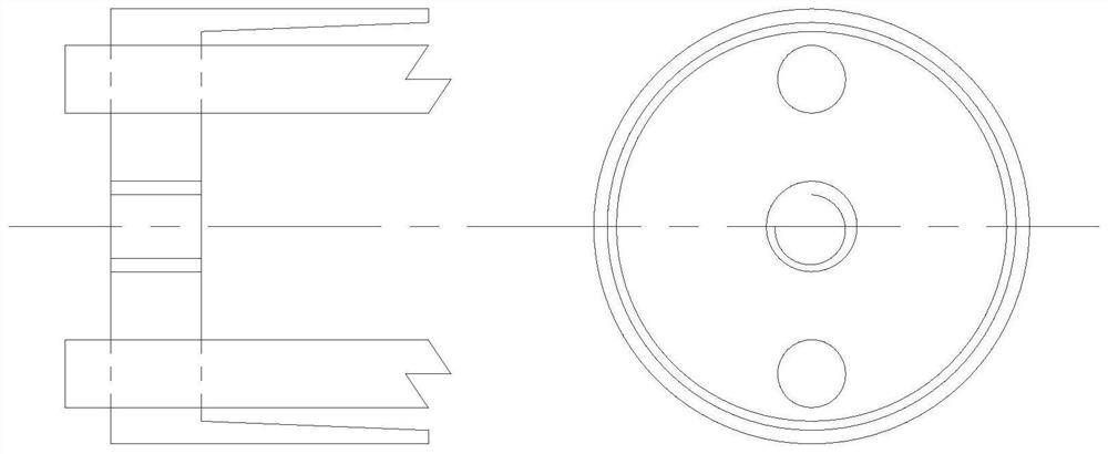
[0050] Described plugging plug near hole bottom part 5 and plugging plug near orifice part 6, such as figure 1 , 2 As shown, they are all cylindrical structures with one end open to match the diameter of the ...


PUM


Abstract

The invention discloses a movable installation device and installation method of a microseismic sensor, wherein the device includes a grouting installation assembly and a grouting assembly, the grouting installation assembly includes an exhaust pipe, a grouting pipe and several wave guide rods, and the grouting assembly The assembly includes the part of the plug near the bottom of the hole, the part of the plug near the orifice and the compression nut; both parts of the plug are cylindrical structures with one end open, and the bottom is equipped with an exhaust pipe through hole, injection The through hole of the slurry pipe and the through hole of the probe; the overall structure of the probe obtained by connecting several probes end to end in turn, together with the exhaust pipe and the grouting pipe, all pass through the corresponding through holes on the grouting component, and the top guide The part of the wave rod protruding out of the plug near the hole is connected with the compression nut, and the compression nut is pushed by the external force to embed the part of the plug near the hole into the inner surface of the plug near the bottom of the hole, so that the plug is close to the bottom of the hole. The bottom part of the hole expands radially; in addition, the overall structure of the probe protrudes from the top of the compression nut and is fixedly connected with the microseismic sensor. The invention can ensure the sealing quality and achieve the purpose of no slurry leakage.

Description

technical field [0001] The invention belongs to the technical field of microseismic monitoring, and in particular relates to a movable installation device and an installation method of a microseismic sensor. Background technique [0002] With the gradual transfer of mining to the deep, the ground stress is getting bigger and bigger. After the excavation of the roadway and stope, the internal stress of the rock mass is transferred and redistributed. Under the dynamic disturbance such as blasting, dynamic disasters such as rockburst and roof collapse are prone to occur, resulting in serious casualties and equipment damage, resulting in a large number of direct and indirect economic losses. loss. [0003] In order to obtain the distribution and occurrence rules of microseismic events inside the rock mass after the excavation of the rock mass, and then analyze the transfer and change trend of the internal stress of the rock mass, and provide a basis for early warning of potenti...

Claims


Application Information

Patent Timeline
Patent Type & Authority Patents(China)
IPC IPC(8): G01V1/20G01V1/28E21B33/12E21B33/13
CPCE21B33/12E21B33/13G01V1/20G01V1/288G01V2210/1429
Inventor 李夕兵孙道元董陇军
Owner CENT SOUTH UNIV
Learn More