Wall board of support

A wall panel and wall surface technology, applied to the parts of the instrument, rack/frame structure, instrument, etc., can solve the problems of waste and high cost

Inactive Publication Date: 2003-05-14
KAWAMURA ELECTRIC INC
View PDF0 Cites 1 Cited by
  • Summary
  • Abstract
  • Description
  • Claims
  • Application Information

AI Technical Summary

Problems solved by technology

[0003] Like this, because on each wall surface of bracket main body 10, when wanting to change the specification of wall surface, even if slightly different in structure also will replace all panels, the expense of spending on specification change is big, because the panel that takes off becomes waste material, causes a lot of problems. waste

Method used


Image

  • Wall board of support
  • Wall board of support
  • Wall board of support

Examples


Embodiment Construction

[0012] specific implementation

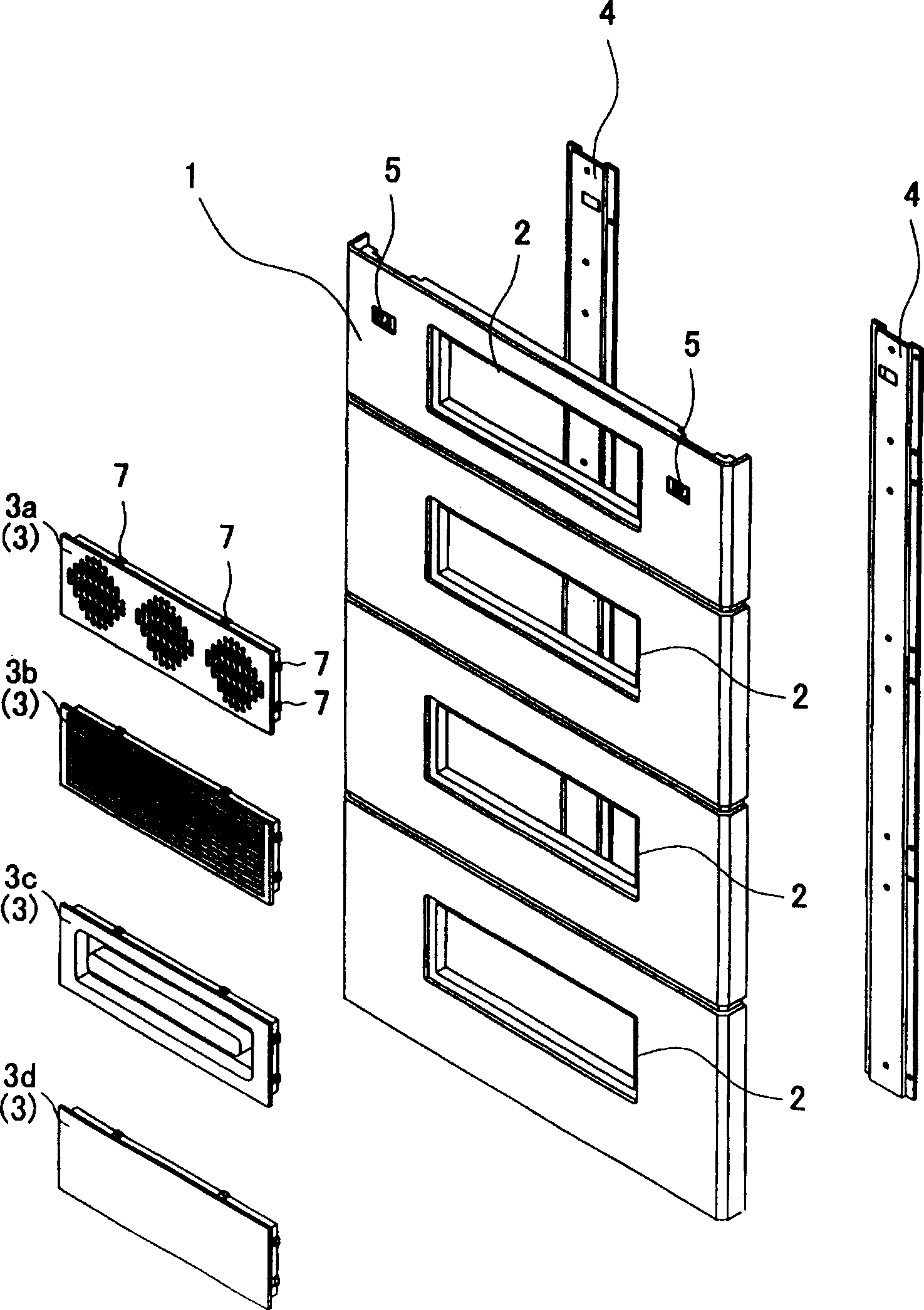
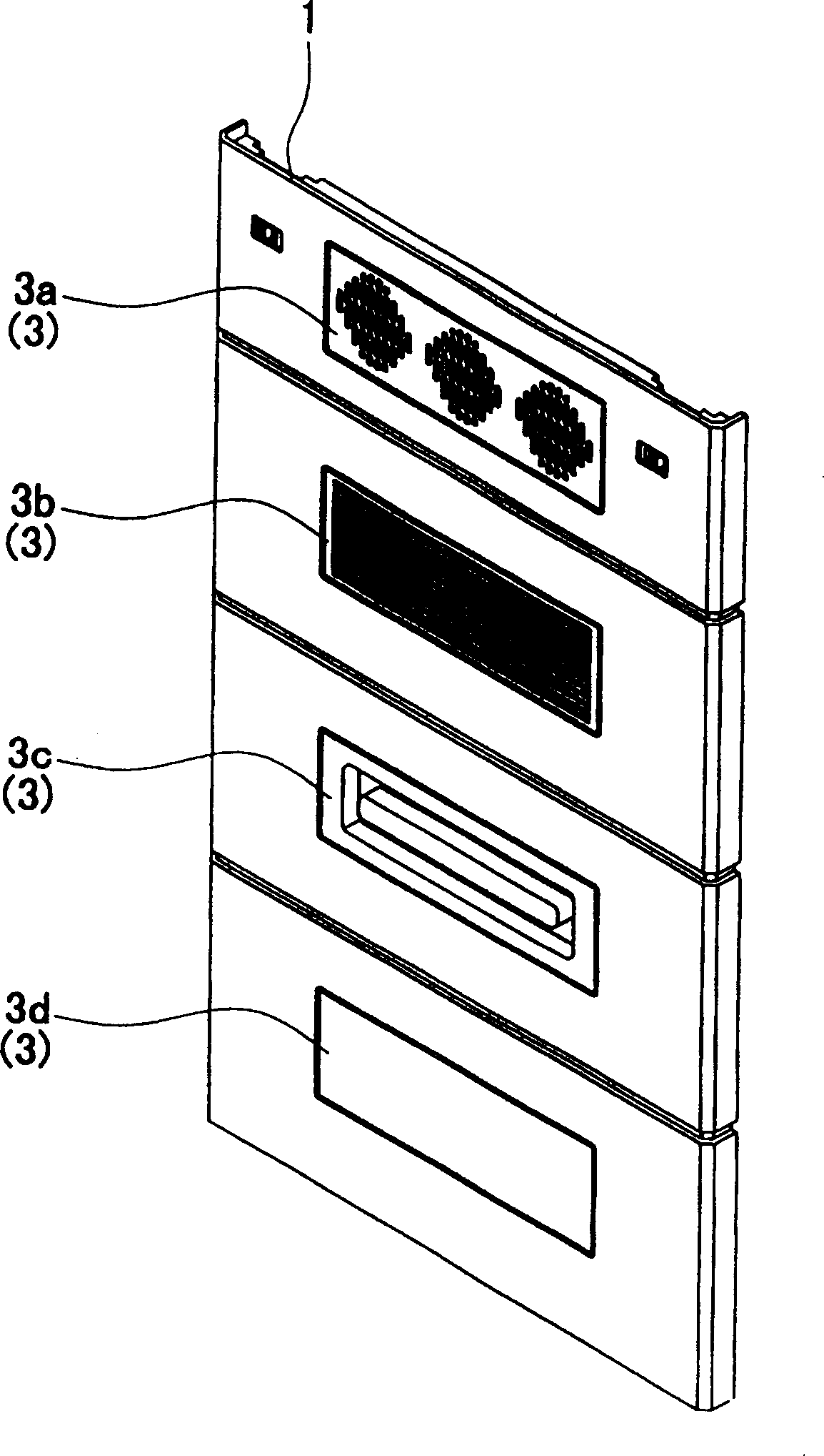
[0013] Embodiments embodying the present invention will be described in detail below with reference to the accompanying drawings. figure 1 It is an exploded oblique view of the wall panel of the bracket related to the present invention, figure 2 Indicates its assembled state. In the figure, 1 is a wall panel body having four openings 2, 3 (3a...3d) is a functional panel attached to the opening 2 of the wall panel body 1 according to the specifications, and 4 is a wall panel arranged on the wall panel The support rods on the left and right sides of the main body 1.

[0014] The wall panel main body 1 has a shape to cover wall surfaces (not shown) such as the side surface and the back surface of the bracket to be attached, and is formed by resin molding. The opening part 2 is formed in four steps up and down, and any one of them is a horizontally wide rectangle and is formed in the same size. Furthermore, well-known attachment levers 5 are ...


PUM


Abstract

The present inventive wall-surface panel for pack eliminates the need of exchanging the whole wall surface of a rack even when the specification of the wall surface is changed and, in addition, reduces the quantity of the destruction rubbish material produced when the wall surface is exchanged. The main body 1 of a wall-surface panel having vertically arranged four openings 2 of the same shape is formed by molding a resin, and functional panels 3 having the same shape as the openings 2 have are fitted into the openings 2. Each functional panel 3 is constituted of an ventilator panel 3a incorporating fans, a slit panel 2b having ventilating holes, a carrying handle panel 3c provided with a carrying handle, a blank panel 3d which only blocks the opening 2, and so on. The functional panels 3 are made attachable and detachable to and from the opening 2. The main body 1 of the wall-surface panel is reinforced by fitting metallic supporting bars 4 to the left and right sides of the back face of the main body 1.

Description

technical field [0001] The present invention relates to a wall surface of a bracket such as a box body or a cabinet body for accommodating electronic equipment, in particular to a wall plate of a bracket formed by a panel. Background technique [0002] For example, conventional brackets such as cabinets or boxes that house electronic equipment are attached to the side or back wall. image 3 , Figure 4 One panel shown to form a wall. image 3 Shown are the holder main body 10 and the empty panel 11 without an opening or the like for sealing the side surface 10a as the wall portion thereof. also, Figure 4 Shown is the ventilation panel 12 provided with the ventilation ports 13 at the upper and lower sides for closing the side surface 10a of the holder main body 10 . and, image 3 , Figure 4 The same panels are also provided on opposite sides and backs. [0003] In this way, when changing the specifications of the walls of the bracket main body 10, even if there is a sli...

Claims


Application Information

Patent Timeline
IPC IPC(8): H05K7/18G12B9/10
Inventor 村濑晴彦
Owner KAWAMURA ELECTRIC INC
Why Eureka
Try Eureka